
S-band low-noise amplifier with self-adjusting bias for improved power consumption and dynamic range in a mobile environment

a low-noise amplifier and mobile environment technology, applied in low-noise amplifiers, gain control, transmission, etc., can solve the problems of system consuming as little power as possible, difficult to predict the jamming environment to which the system will be exposed, and long battery life, so as to achieve low noise, high dynamic range, and low power consumption

Inactive Publication Date: 2010-08-24
RGT UNIV OF CALIFORNIA
View PDF29 Cites 52 Cited by
  • Summary
  • Abstract
  • Description
  • Claims
  • Application Information

AI Technical Summary

Benefits of technology

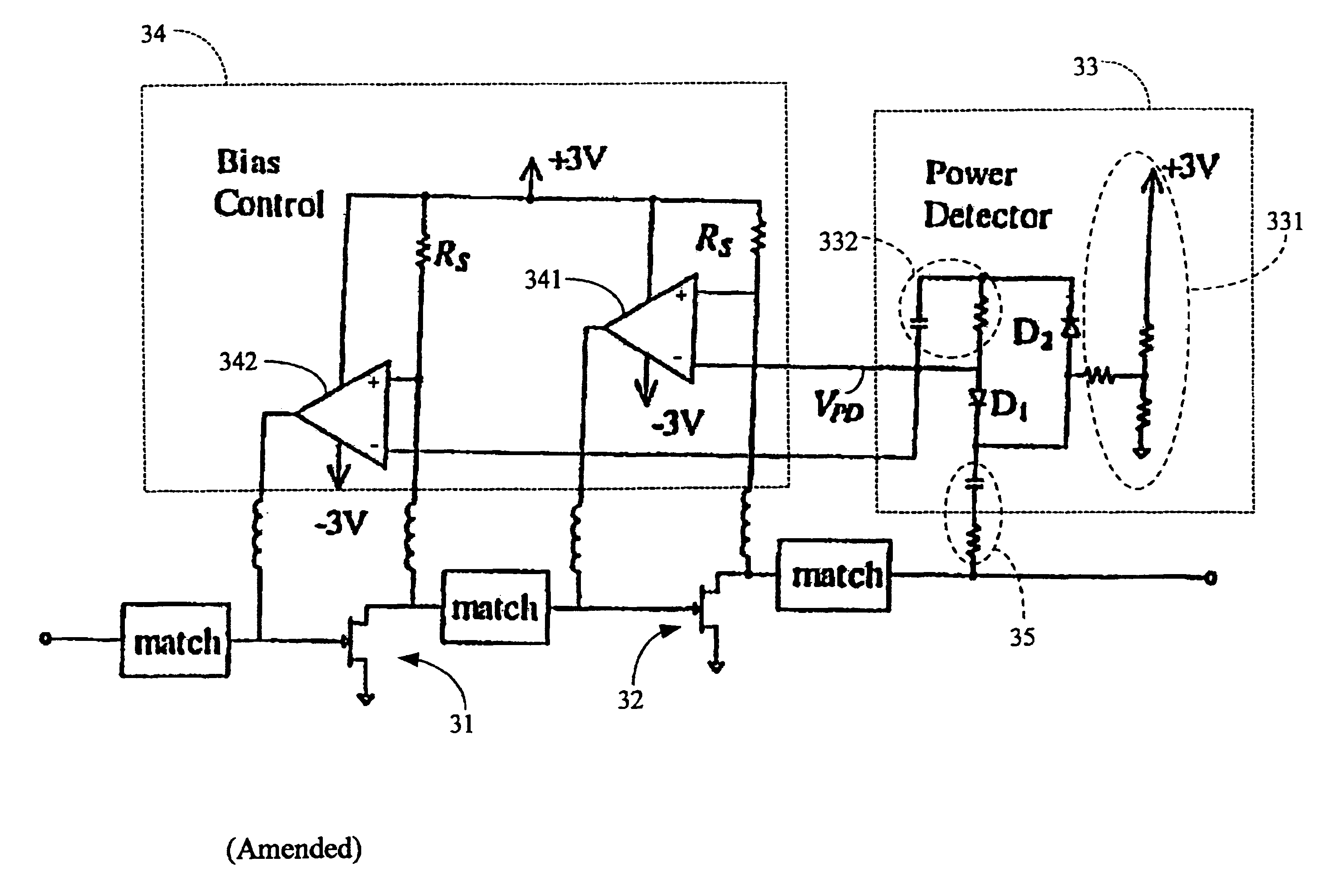
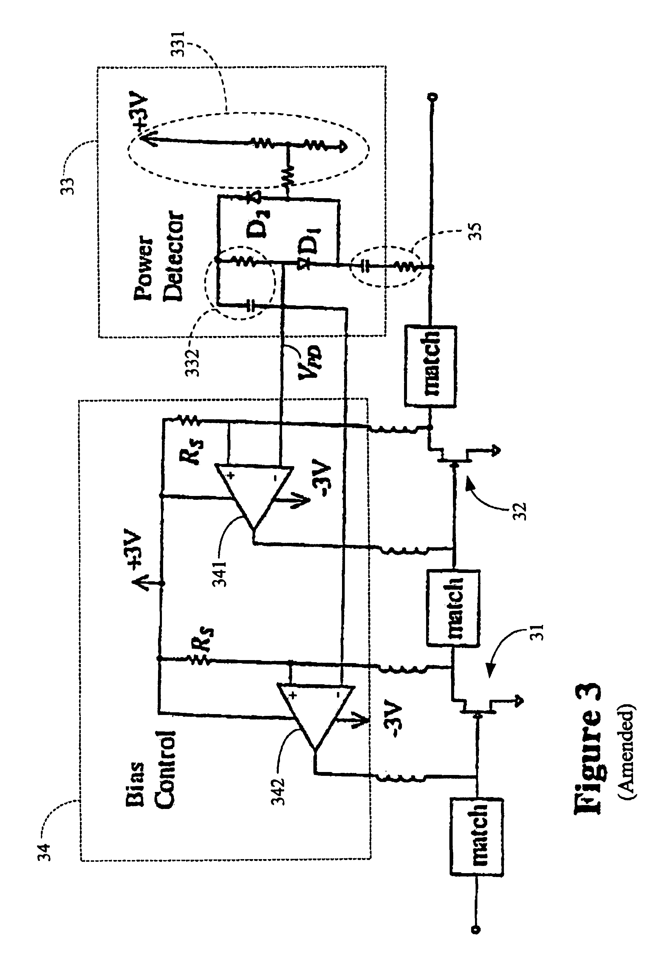
[0010]The present invention contemplates a Low Noise Amplifier (LNA) that circumvents the compromise between (i) dynamic range and (ii) power consumption by optimizing power consumption for the operating environment. The LNA of the present invention exhibits a high dynamic range when it is near or in compression, but low power consumption when it is in small-signal operation where a large dynamic range is not necessary.
[0011]Furthermore, the dynamic range of the amplifier is extended: jamming may be countenanced without such distortion as would otherwise occur.

Problems solved by technology

This is especially true for a mobile communication system, such as a cellular phone, as it is difficult to predict the jamming environment the system will be exposed to.
At the same time, the need for portability, and thus long battery life, requires the system to consume as little power as possible.
However, a high rejection ratio incurs high insertion loss—a direct contributor of receiver sensitivity degradation.
In addition, many close-in jammers are impossible to block given the size and cost restrictions of a mobile system.
To meet these demands, the LNAs often consume the most power in a receiver; tradeoffs are usually required to balance dynamic range versus power consumption.

Method used


Image

  • S-band low-noise amplifier with self-adjusting bias for improved power consumption and dynamic range in a mobile environment
  • S-band low-noise amplifier with self-adjusting bias for improved power consumption and dynamic range in a mobile environment
  • S-band low-noise amplifier with self-adjusting bias for improved power consumption and dynamic range in a mobile environment

Examples


Embodiment Construction

[0053]The present invention is embodied in a Low Noise Amplifier (LNA) circuit of new design. The LNA is particularly useful in a cellular, mobile, wireless radio communications system where jamming is occasionally experienced.

1. The Operational Environment

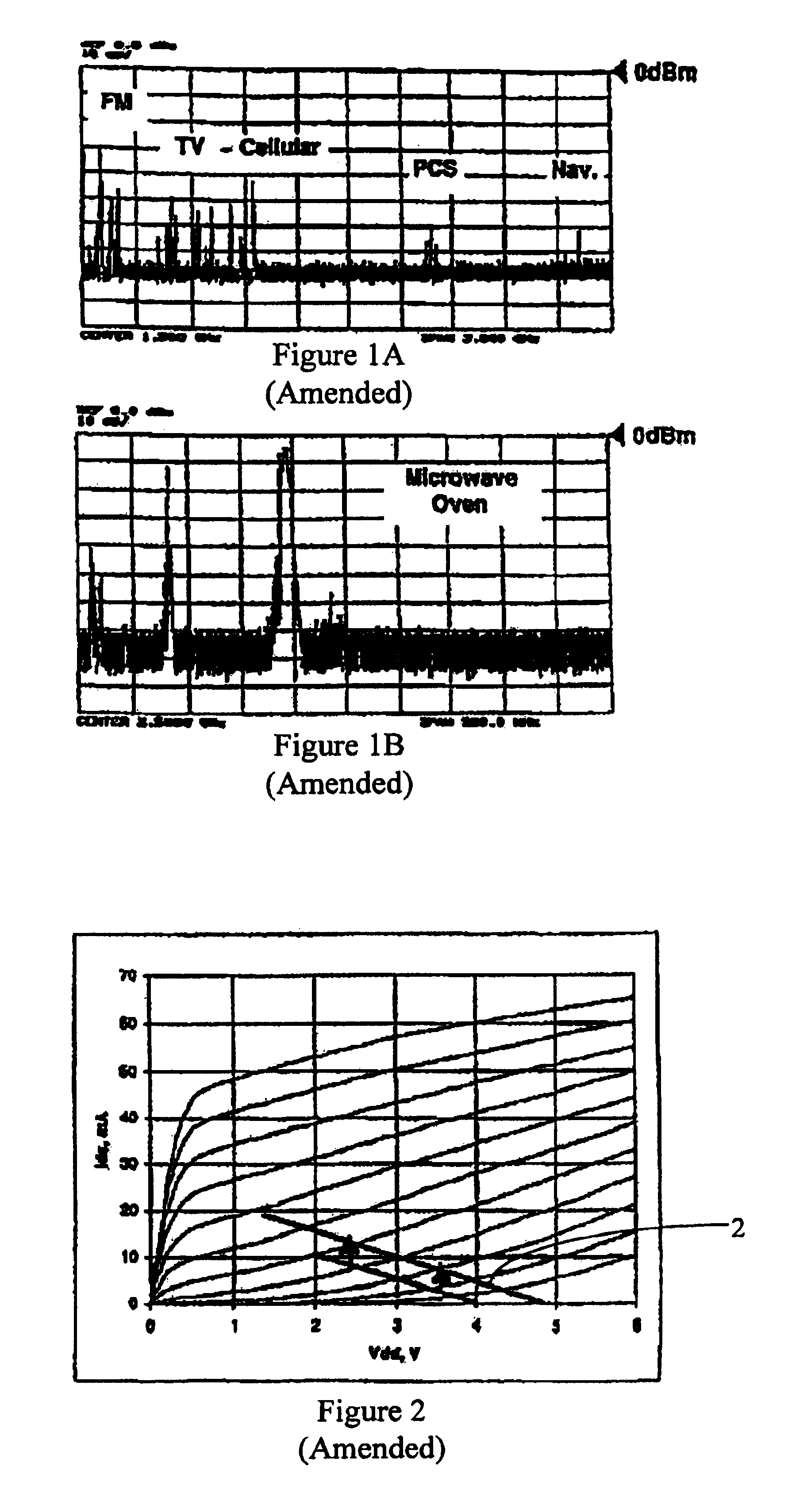
[0054]FIG. 1, consisting of FIGS. 1a and 1bFIGS. 1A and 1B, illustrates some typical jammers as measured by an omni-directional 2.5 GHz antenna. Sources of a microwave oven, a navigational beacon (“nav.”), a personal communication system cellular telephone (“PCS”), an analog cellular telephone (“Cellular”), television (“TV”) and frequency modulation radio (“FM”) are in particular illustrated. To avoid fatal interference from these jamming signals a low-noise amplifier must have a large dynamic range: namely, a low noise figure and low intermodulation distortion. See S. Chen, “Linearity Requirements for Digital Wireless Communication,” IEEE GaAs IC Symp. Dig., At Anaheim, Calif., pp. 29-32, October 1997.

[0055]To meet these demands,...


PUM


Abstract

A discrete low-noise amplifier designed to operate in a mobile wireless environment uses two cascaded GaAs FETs to achieve 25 dB gain and 0.9 dB noise figure at 2.5 GHz. Active bias control circuitry responsive to monitored amplifier output power automatically and continuously adjusts the drain-source currents, and the load lines, of the cascaded FETs to (i) maintain power consumption at 33 milliwatts in nominal small-signal conditions, and to (ii) provide an elevated input third-order intermodulation intercept point (IP3) and a reduced noise figure during the presence of jamming. A 15 dB improvement in the input IP3 is achieved in large-signal operation. Amplifier operation is supported by an a.c. power detector of enhanced sensitivity and responsiveness because of un-grounded operation.

Description

BACKGROUND OF THE INVENTION[0001]1. Field of the Invention[0002]The present invention generally concerns amplifier design and amplifier operation, particularly for wireless cellular radio communications applications where occasional jamming is prevalent.[0003]The present invention particularly concerns the realization by both design and operation of a Low Noise Amplifiers (LNA) simultaneously improved in (i) dynamic range and (ii) overall power consumption, these seemingly contradictory requirements being satisfied by optimizing power consumption in the LNA in consideration of its instant operating environment.[0004]The present invention further particularly concerns an ungrounded power detector that is both fast and sensitive to detect the output power of, for example, a LNA.[0005]2. Description of the Prior Art2.1 Low Noise Amplifiers, and Amplifier Operation in the Presence of Jamming[0006]With the explosive growth of wireless communications, the airwaves are rapidly being filled...

Claims


Application Information

Patent Timeline
IPC IPC(8): H04B1/06H03F1/02H03G3/30
CPCH03F1/0272H03F2200/105H03F2200/15H03F2200/222H03F2200/294H03F2200/318H03F2200/372H03F2200/387H03F2200/411H03F2200/451H03G3/3042
Inventor LARSON, LAWRENCEXIONG, WEI
Owner RGT UNIV OF CALIFORNIA
Learn More