
WDM multiplexing/de-multiplexing system and the manufacturing method thereof

a manufacturing method and multiplexing technology, applied in the field of photoelectric conversion components, can solve the problems of affecting the transmission performance of high speed digital electrical signals, and conventional mux/demux systems may have a relatively low yield

Active Publication Date: 2020-06-02
SOURCE PHOTONICS
View PDF31 Cites 1 Cited by
  • Summary
  • Abstract
  • Description
  • Claims
  • Application Information

AI Technical Summary

Benefits of technology

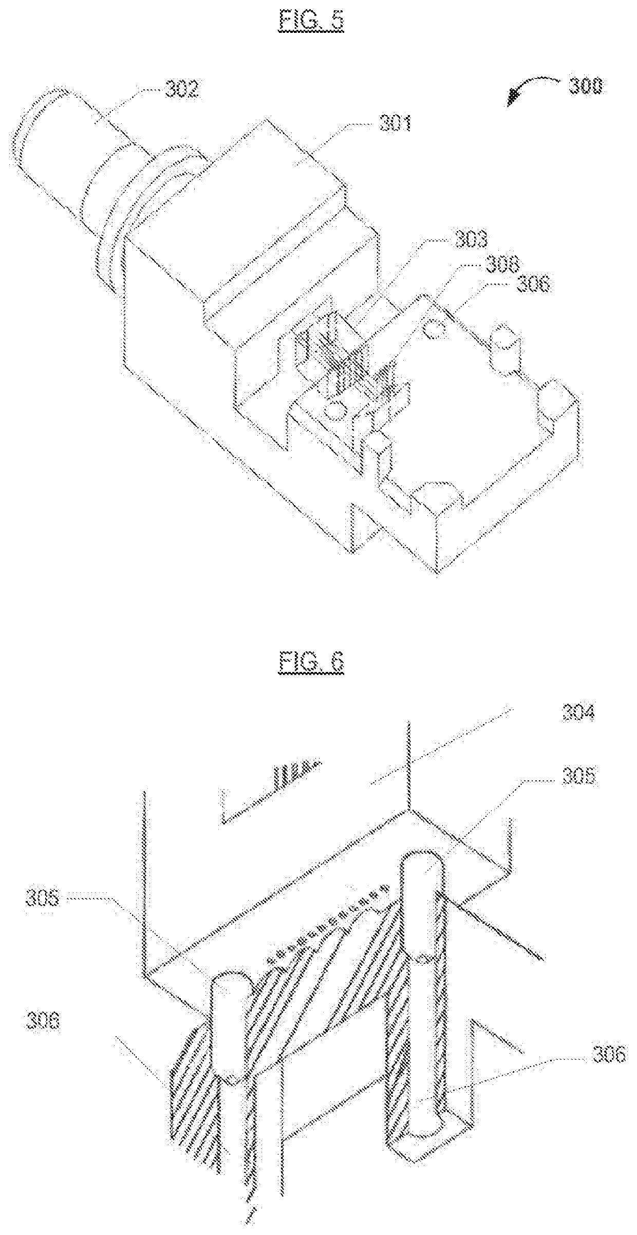
This patent describes a new design for plastic optical devices used in high-speed data transmission. The design includes alignment holes and a mechanical transfer guiding system to ensure precise positioning of the components during assembly. This improves the yield of the optical devices and reduces optical power loss caused by misalignment. The design also reduces the length of the electrical transmission path, simplifies the manufacturing process, and increases the optical signal-to-noise ratio. Overall, this patent introduces a more efficient and reliable design for plastic optical devices.

Problems solved by technology

However, there are some issues with these conventional techniques.
Typically, relatively long electrical circuits negatively affect the transmission performance of high speed digital signals.
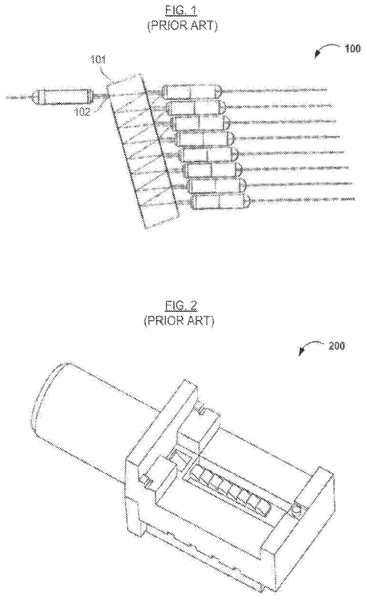
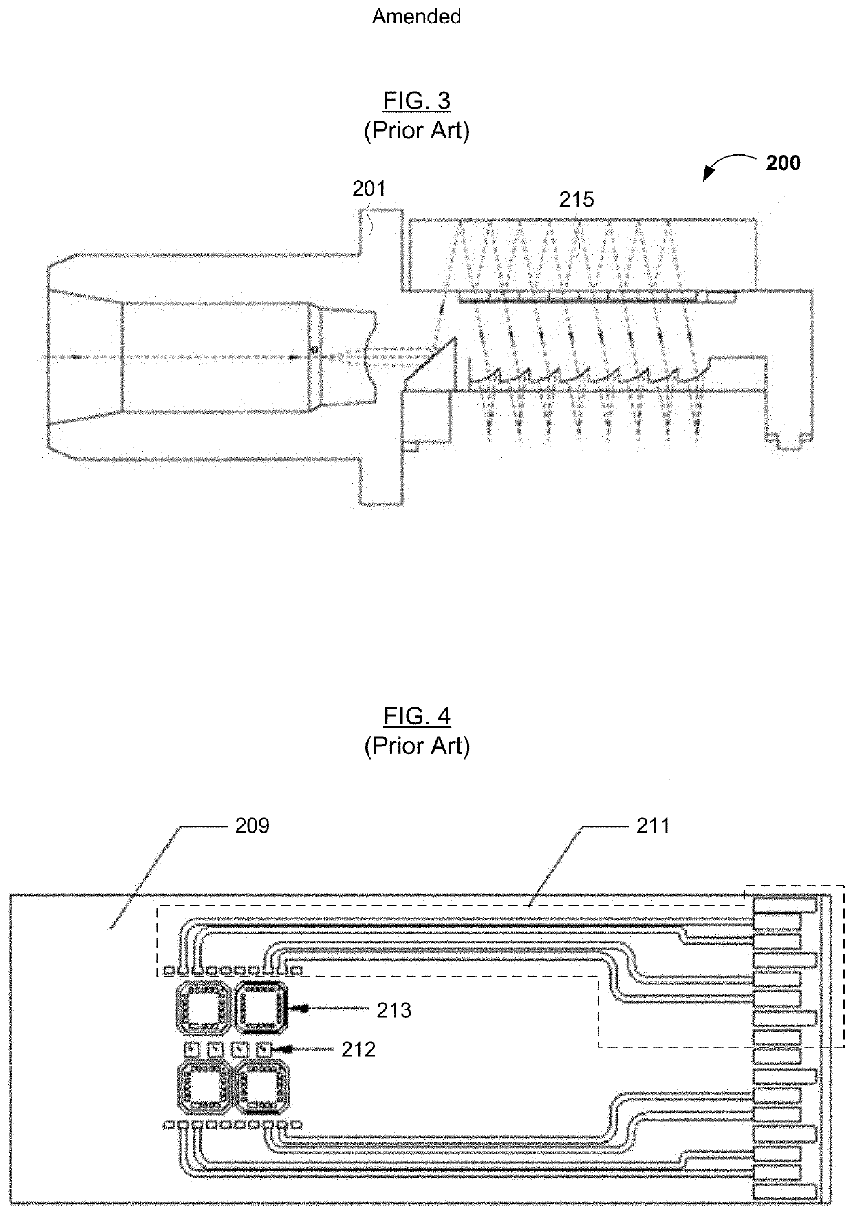
One issue with the conventional MUX / DEMUX system(s) shown in FIGS. 2 and 3 is that a lens array having an arrangement parallel with incident light can affect the transmission performance of high speed digital electrical signals at the back-end of a fiber-optic communication device.
As a result, conventional MUX / DEMUX systems may have a relatively low yield.

Method used


Image

  • WDM multiplexing/de-multiplexing system and the manufacturing method thereof
  • WDM multiplexing/de-multiplexing system and the manufacturing method thereof
  • WDM multiplexing/de-multiplexing system and the manufacturing method thereof

Examples


Embodiment Construction

[0038]Reference will now be made in detail to various embodiments of the invention, examples of which are illustrated in the accompanying drawing(s). In order to achieve the objectives, technical solutions and advantages of the present invention more clearly, further details of the invention are described below with regard to the Figure(s). While the invention will be described in conjunction with the following embodiments, it will be understood that the descriptions are not intended to limit the invention to these embodiments. On the contrary, the invention is intended to cover alternatives, modifications and equivalents that may be included within the spirit and scope of the invention as defined by the appended claims. Furthermore, in the following detailed description, numerous specific details are set forth in order to provide a thorough understanding of the present invention. However, it will be readily apparent to one skilled in the art that the present invention may be practi...


PUM


Abstract

A WDM multiplexing / demultiplexing system includes a de-multiplexer configured to separate and guide light beams from an incident ray having a plurality of wavelengths to corresponding lenses on an optical device, a multiplexer configured to guide light beams from optical transmitters having various wavelengths through the corresponding lenses on the optical device and combine the light beams, a lens array including the corresponding lenses to receive and / or transmit the light beams from or to the de-multiplexer and multiplexer, and a light beam collimator configured to function with the multiplexer and de-multiplexer. The light beams received or transmitted by the light beam collimator and the light beams transmitted or received from or to the multiplexer and de-multiplexer are collinear. The light beam collimator and multiplexer / de-multiplexer can be easily positioned to predetermined or designed positions, thereby providing light beams output through the lenses in a plastic optical device. The WDM system advantageously reduces optical signal loss, while increasing the assembly yield.

Description

CROSS REFERENCE TO RELATED APPLICATION[0001]This application claims the benefit of Chinese Patent Application No. 201210402718.4, filed on Oct. 22, 2012, incorporated herein by reference as if fully set forth herein.FIELD OF THE INVENTION[0002]The present invention relates to a photoelectric conversion component in fiber optic data communications and telecommunications. In particular, embodiments of the present invention pertain to a wavelength division multiplexing (WDM; e.g., a coarse wavelength division multiplexing [CWDM] / de-multiplexing system and a manufacturing method thereof.DISCUSSION OF THE BACKGROUND[0003]Coarse wavelength division multiplexing (CWDM) is a technology that multiplexes multiple optical signals on a single optical fiber strand by using different wavelengths of laser light to carry different signals. There are two conventional CWDM systems. One conventional CWDM system is formed by single wavelength optical communication modules using an external multiplexer / ...

Claims


Application Information

Patent Timeline
Patent Type & Authority Patents(United States)
IPC IPC(8): G02B6/28G02B6/293G02B27/12G02B6/42
CPCG02B6/4215G02B6/425G02B6/29367G02B6/2938G02B27/123Y10T29/49004Y10T29/49769
Inventor CHANG, YUNG-CHENGCHOU, EMINKUO, KEN
Owner SOURCE PHOTONICS
Learn More