A non-traumatic interfere treatment system
An interventional therapy and drug technology, applied in the field of therapeutic systems, can solve problems such as unfavorable drug absorption and small effective injection area, and achieve the effects of reducing use costs and solving installation and waste.
- Summary
- Abstract
- Description
- Claims
- Application Information
AI Technical Summary
Problems solved by technology
Method used
Image
Examples
Embodiment 1
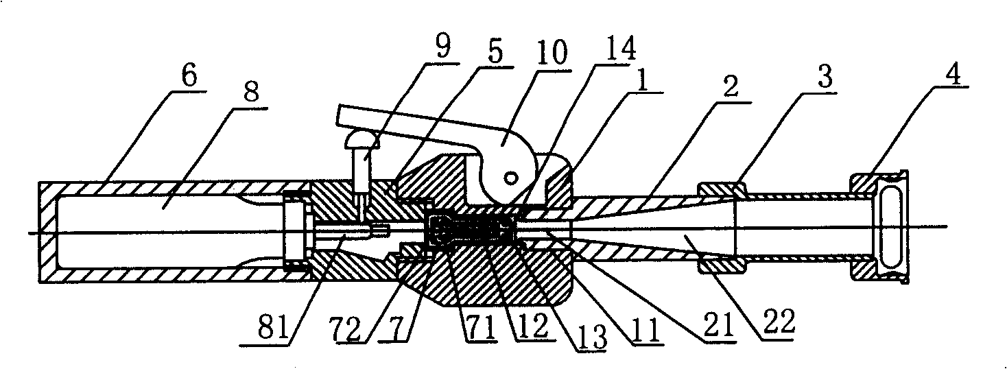
[0017] Embodiment 1: A non-invasive interventional treatment system, including a main body 1, a high-speed nozzle 2, an air guide tube 3, an air guide seat 4, a connecting seat 5 and an air storage tank 6, and the main body 1 is provided with a drug ejection port 11 and a drug ejection port 11 communicates with the inner cavity 12, and the inner cavity 12 is provided with a sonic nozzle 13 near the drug ejection port 11, and the high-speed nozzle 2 is screwed on the drug ejection port 11, and the outlet of the sonic nozzle 13 is arranged between the entrance of the high-speed nozzle 2 There is a certain distance to form a low-pressure Venturi zone 14. The part of the high-speed nozzle 2 close to the medicine ejection port 11 is a parallel part 21 of equal inner diameter, and the front part is a horn-shaped diffuser part 22. 2, the air guide tube 3 is a cylindrical member with the same inner diameter as the maximum inner diameter of the diffusion part 22, the air guide seat 4 is...
Embodiment 2
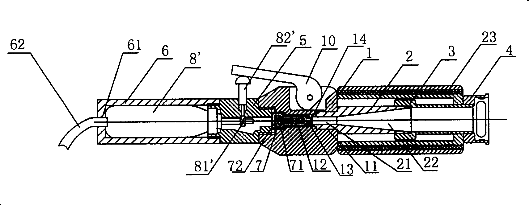
[0018] Embodiment 2: Other structures are the same as Embodiment 1, the difference is that the bottom of the gas storage tank 6 is provided with an air supply hole 61, and the disposable high-pressure gas cylinder 8 in the gas storage tank 6 is replaced by a gas storage cylinder 8', and the gas storage cylinder 8' An air supply pipe 62 is arranged on the top, and the air supply pipe 62 communicates with an external gas cylinder (not shown) through the air supply hole 61. An air supply valve 81' is arranged on the front of the gas storage cylinder 8', and a valve is arranged on the air supply valve 81' The control rod 82', the valve control rod 82' passes through the connecting seat 5 and is connected to one end of the pressing handle 10. The high-speed nozzle 2 and the air pipe 3 are coaxially sleeved with a silencer 23, and the silencer 23 is screwed on the air pipe. 4 on.
Embodiment 3
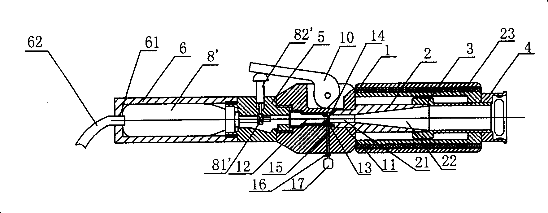
[0019] Embodiment 3: other structures are the same as Embodiment 2, the difference is that the cartridge case 7 arranged in the inner cavity 11 is removed, and the drug supply channel 15 is set on the main body 1, and the outlet of the drug supply channel 15 is arranged at the sonic nozzle At the low-pressure Venturi area 14 between the outlet of 13 and the entrance of the high-speed nozzle 2, a dosing valve 16 is set at the entrance of the medicine supply channel 15, and the dosing valve 16 is provided with an external medicine box interface, and the external medicine box 17 is set On the dosing valve 16 , it communicates with the medicine supply channel 15 through the dosing valve 16 .
PUM
 Abstract
Description
Claims
Application Information
 - R&D
- Intellectual Property
- Life Sciences
- Materials
- Tech Scout
- Unparalleled Data Quality
- Higher Quality Content
- 60% Fewer Hallucinations
Browse by: Latest US Patents, China's latest patents, Technical Efficacy Thesaurus, Application Domain, Technology Topic, Popular Technical Reports.
© 2025 PatSnap. All rights reserved.Legal|Privacy policy|Modern Slavery Act Transparency Statement|Sitemap|About US| Contact US: help@patsnap.com


