
Self-adapting technique changing method for self-adapting focusing and leveling adjustment sensor system

A technology for focusing, leveling, and process change, which is applied in photolithographic process exposure devices, semiconductor/solid-state device manufacturing, electrical components, etc., and can solve the problems of complicated scanning control, increased exposure failure rate and scrap rate, and low production efficiency, etc. problems, to achieve the effects of improving usability, production efficiency and yield, reducing measurement errors and system failure risks, and saving use costs

Active Publication Date: 2009-04-01
SHANGHAI MICRO ELECTRONICS EQUIP (GRP) CO LTD
View PDF6 Cites 0 Cited by
  • Summary
  • Abstract
  • Description
  • Claims
  • Application Information

AI Technical Summary

Problems solved by technology

First of all, the customer needs to make a corresponding spot switching table according to the specific characteristics of focusing and leveling, as well as each type of silicon wafer and the different layers of a type of silicon wafer, and needs to input this information into the In the lithography machine, this not only requires a large number of process experiments, but also needs to input a large amount of work definition data content during the work process, which increases the cost and difficulty of using the entire lithography machine, and also reduces the cost of the lithography machine. The production efficiency of the machine; secondly, the use of the spot switching table will also complicate the scanning control and the processing of the focus and leveling data; thirdly, due to the deterioration of the flatness of the photoresist on different silicon wafers or different positions in the same silicon wafer The characteristics such as the degree of degradation and deterioration do not fully follow the pre-delineated geometric boundaries of the inner field, the interface field, and the outer field. The practice of uniformly delineating the reliability boundary for a class of silicon wafers or a certain layer of silicon wafers may lead to focusing Leveling uses originally unreliable information or discards originally reliable information, which increases exposure failure rate and scrap rate to a certain extent
[0006] For the overflow problem of electronic components in the focusing and leveling system based on photoelectric detection, the existing technology also adopts the method of firstly conducting process tests and measurements, and then manually inputting the corresponding automatic gain factor in the signal processing circuit, and its disadvantage is also in production. A large number of process tests are required in the process, and the operator also needs to input corresponding selection data, which makes the use of the entire lithography machine more difficult and the production efficiency is low

Method used


Image

  • Self-adapting technique changing method for self-adapting focusing and leveling adjustment sensor system
  • Self-adapting technique changing method for self-adapting focusing and leveling adjustment sensor system
  • Self-adapting technique changing method for self-adapting focusing and leveling adjustment sensor system

Examples


Embodiment Construction

[0050] The present invention will be further described below in conjunction with the accompanying drawings and examples.

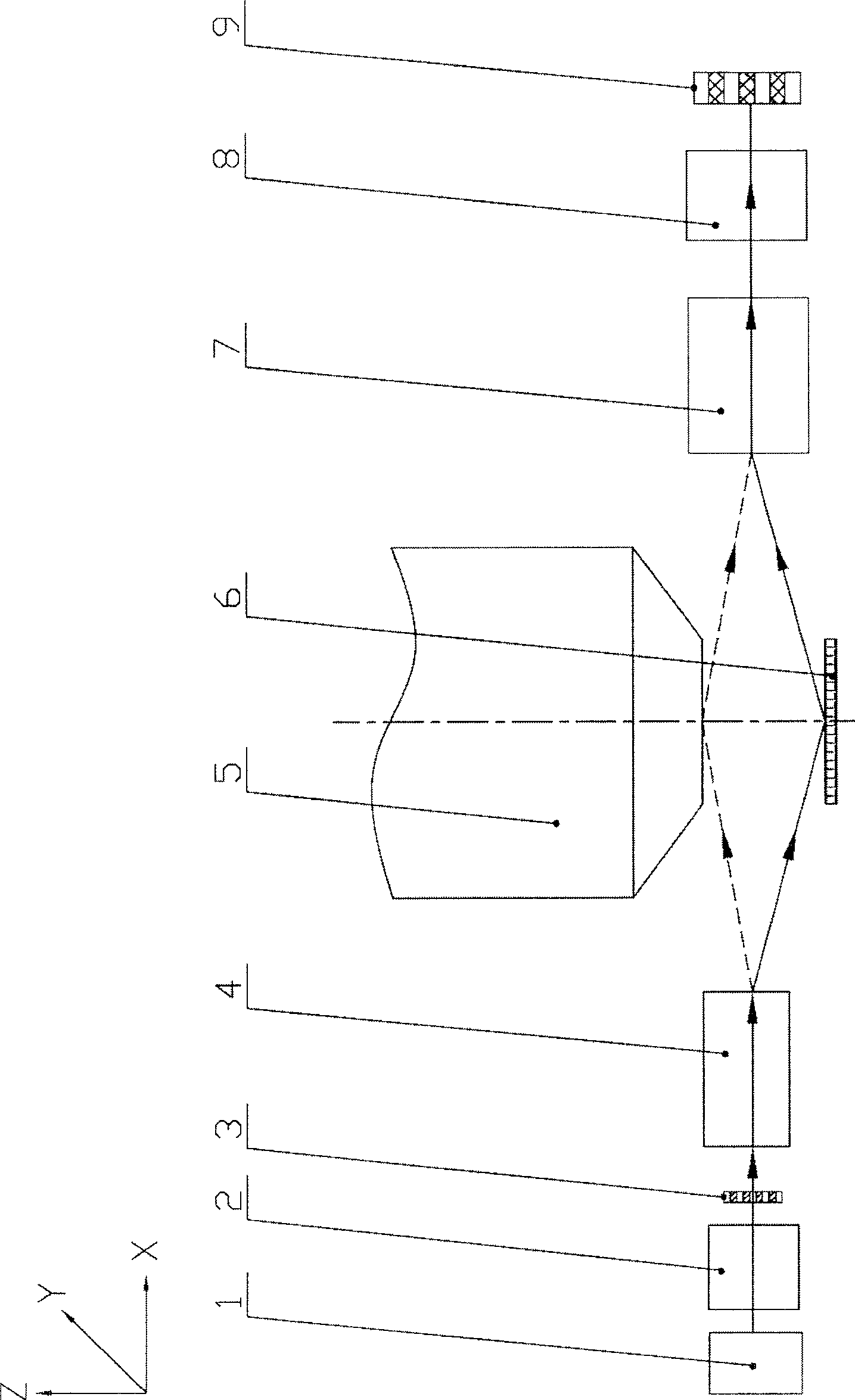
[0051] see image 3 , image 3 It is a structural schematic diagram of a focusing and leveling system based on photoelectric measurement. Such as image 3 As shown, the light emitted from the light source module 1 passes through the illumination optical module 2 for beam shaping, and then passes through the illumination spot mask 3 to generate a spot. The spot mask 3 is designed according to the shape and distribution of the spot that needs to be projected onto the measurement object (silicon wafer or the lower surface of the projection objective lens), and the projection relationship from the spot mask to the measurement object, so as to ensure that the measurement object can produce all Spot distribution is required. The light beam emitted from the spot mask 3 passes through the projection module 4 and then projects onto the measurement object. The m...


PUM


Abstract

An adaptive focusing-leveling transducer system is featured as arranging light through hole being used to form prediction light spot at external of exposure slit on light spot mask and utilizing formed prediction light spot at external of exposure slit to make said adaptive focusing-leveling transducer system realize adaptability on process.

Description

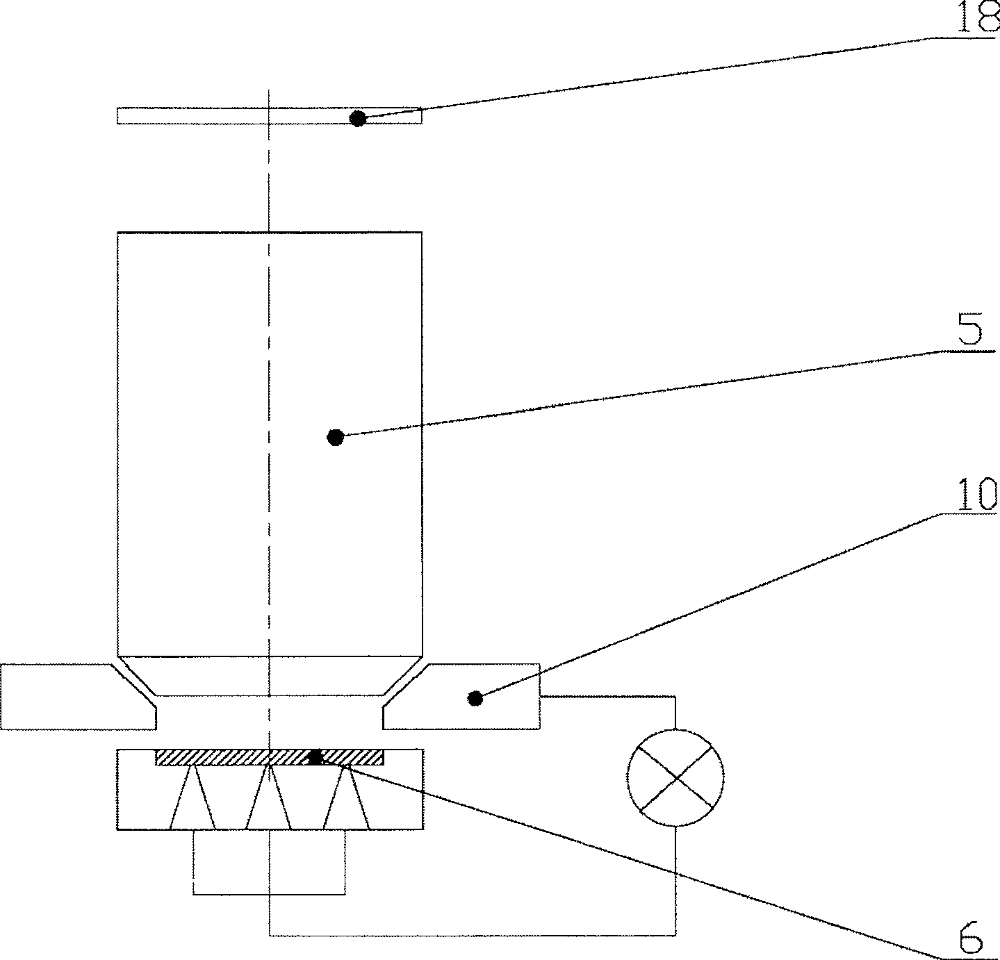
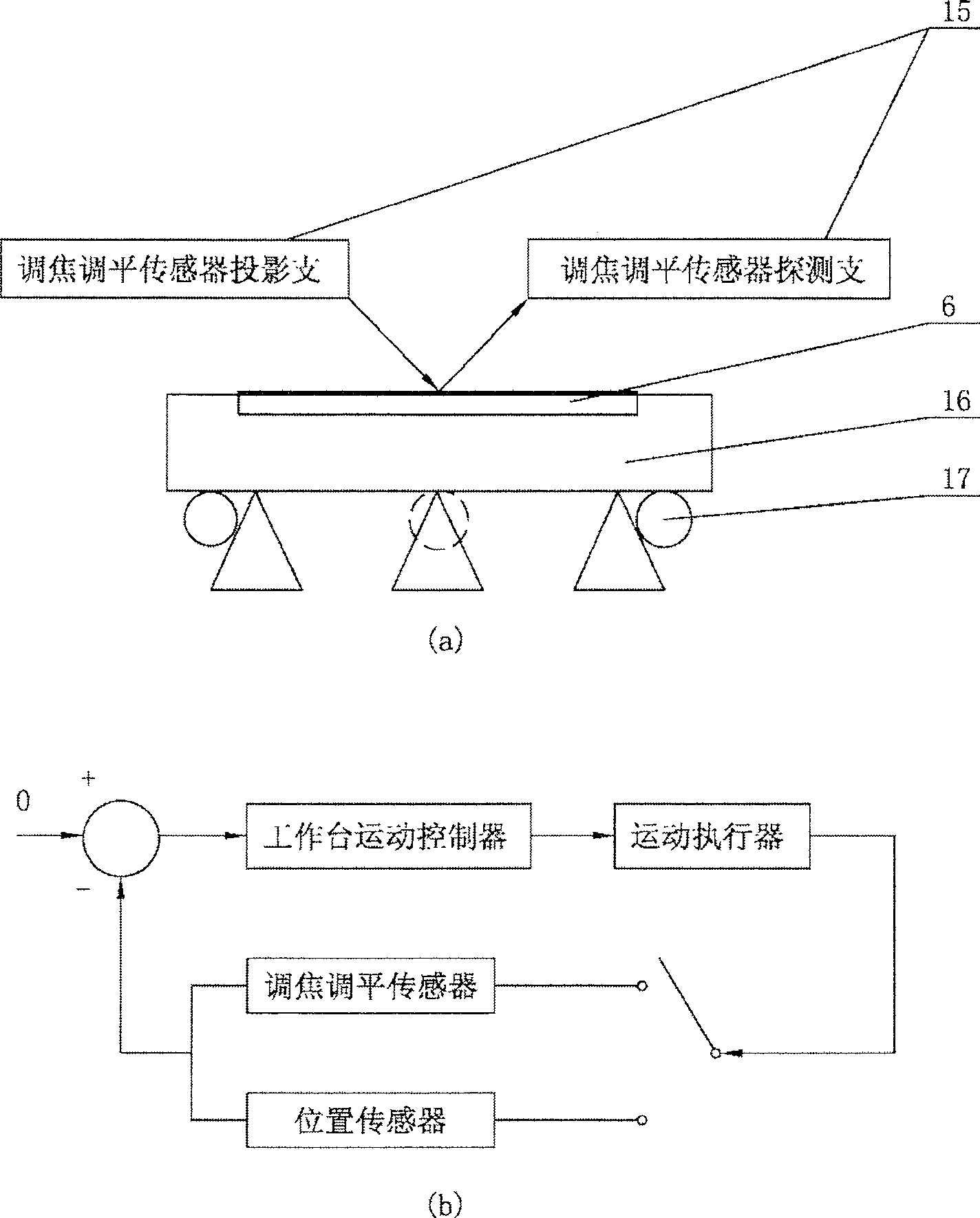
technical field [0001] The invention belongs to the field of focusing and leveling sensors for projection lithography machines, and in particular relates to a focusing and leveling sensor with self-adaptive capability. Background technique [0002] The photolithography machine is an exposure device that transfers the pattern on the mask to the object to be processed (such as silicon wafer, etc.) in a certain proportion. see figure 1 , in the projection lithography machine, the exposure light beam illuminates the mask 18 engraved with the integrated circuit pattern, and the mask 18 is imaged on the silicon wafer 6 of the processing object through the projection objective lens 5 to expose the photoresist coated on the processing object, thereby the The mask pattern is copied to the processing object. In this exposure device, it is necessary to keep the exposed surface of the exposed object within the focal depth range of the projection objective lens in the exposure device, ...

Claims


Application Information

Patent Timeline
Patent Type & Authority Patents(China)
IPC IPC(8): G03F7/20H01L21/027
Inventor 关俊
Owner SHANGHAI MICRO ELECTRONICS EQUIP (GRP) CO LTD
Learn More