Energy-saving cooking utensils
A technology of cooking utensils and cookers, applied in the field of kitchen utensils, can solve the problems of high production cost, complicated gap structure, and affecting the service life of cooking utensils, and achieve the effects of low production cost, increased receiving area, and favorable heat conduction
- Summary
- Abstract
- Description
- Claims
- Application Information
AI Technical Summary
Problems solved by technology
Method used
Image

Examples
Embodiment 1
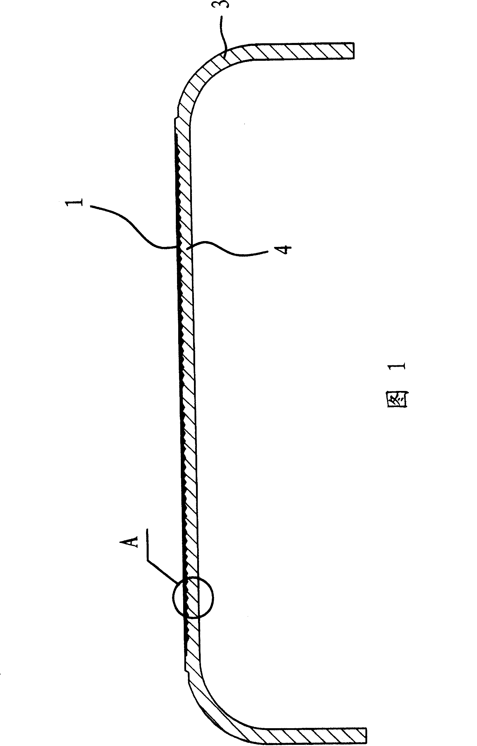
[0037] As shown in Fig. 1, Fig. 2 and Fig. 3, the energy-saving cooking appliance includes a cooker wall 3 and a cooker bottom 4 integrally connected with the cooker wall 3 for being heated.
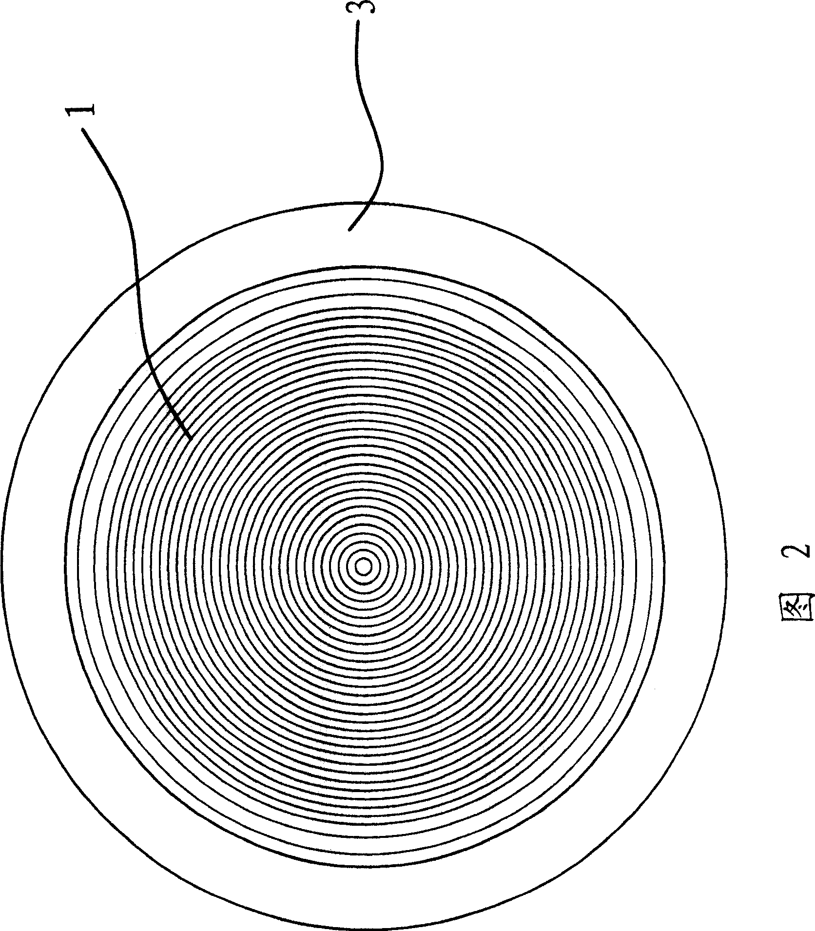
[0038] The outer surface of the cooker bottom 4 is fixed with a corrugated metal sheet 1, and the metal sheet 1 and the cooker bottom 4 are combined together by hot forging or brazing. Sheet 1 is made of ferrite or martensitic stainless steel with strong magnetic flux capability. And the corrugated shape of the metal sheet 1 is a plurality of concentric circular structures with the center of the metal sheet 1 as the center.
[0039] It can be seen that the corrugated metal sheet 1 expands the area of the cooker bottom 4 for receiving electromagnetic waves, and can effectively absorb the electromagnetic energy converted from electric energy and convert it into heat energy, thereby improving the utilization rate of electric energy.
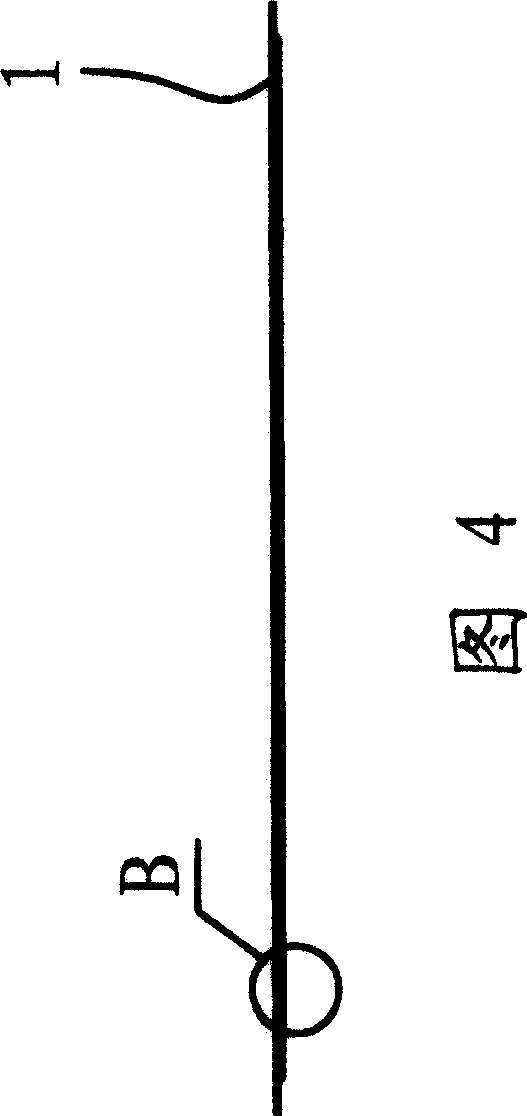
[0040] As shown in FIGS. 4 and 5 , both sides of the ...
Embodiment 2
[0042] As shown in Fig. 6 and Fig. 7 and Fig. 8, the structure and principle of this embodiment are basically the same as that of Embodiment 1, the difference is that a metal plate 2 is arranged between the bottom 4 of the cooker and the metal sheet 1, and the described The outer surface of the metal plate 2 has a corrugated shape with the same shape and size as that of the metal sheet 1. Between the metal sheet 1 and the metal plate 2, and between the metal plate 2 and the bottom of the cooker 4, heat forging or brazing is used. The metal plate 2 is made of aluminum, and the metal plate 2 plays the role of heat conduction and anti-corrosion.
Embodiment 3
[0044] As shown in Fig. 9 and Fig. 10 and Fig. 11, the structure and principle of the present embodiment are basically the same as those of the second embodiment, the difference is that the corrugated shape of the metal sheet 1 is in the shape of dot-like concavo-convex or strip-shaped concavo-convex on the bottom surface, And take the center of the metal sheet 1 as the starting point to form an outward-emitting structure. Of course, the outer surface of the metal plate 2 also has corrugations of the same shape and size as the metal plate 1 or the bottom 4 of the cooker.
PUM
 Abstract
Description
Claims
Application Information
 - R&D
- Intellectual Property
- Life Sciences
- Materials
- Tech Scout
- Unparalleled Data Quality
- Higher Quality Content
- 60% Fewer Hallucinations
Browse by: Latest US Patents, China's latest patents, Technical Efficacy Thesaurus, Application Domain, Technology Topic, Popular Technical Reports.
© 2025 PatSnap. All rights reserved.Legal|Privacy policy|Modern Slavery Act Transparency Statement|Sitemap|About US| Contact US: help@patsnap.com