
Ultraprecise drive mechanism

A drive mechanism, ultra-precision technology, applied in the direction of metal processing machinery parts, metal processing, metal processing equipment, etc., can solve the problems of poor resistance to external interference, low static and dynamic stiffness, etc., to achieve increased static pressure area, load bearing The effect of capacity expansion and simple structure

Inactive Publication Date: 2009-12-09
HARBIN INST OF TECH
View PDF4 Cites 0 Cited by
  • Summary
  • Abstract
  • Description
  • Claims
  • Application Information

AI Technical Summary

Problems solved by technology

[0003] The purpose of the present invention is to provide an ultra-precision drive mechanism to solve the shortcomings of the existing linear motion ultra-precision workbench that the static and dynamic stiffness is low and the ability to resist external interference is poor

Method used


Image

  • Ultraprecise drive mechanism
  • Ultraprecise drive mechanism

Examples


specific Embodiment approach

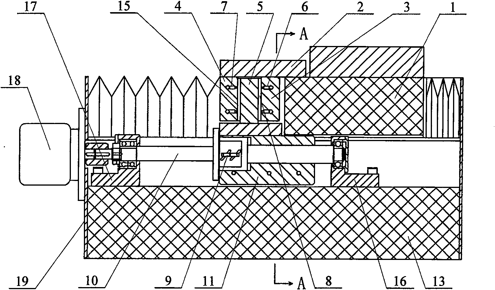
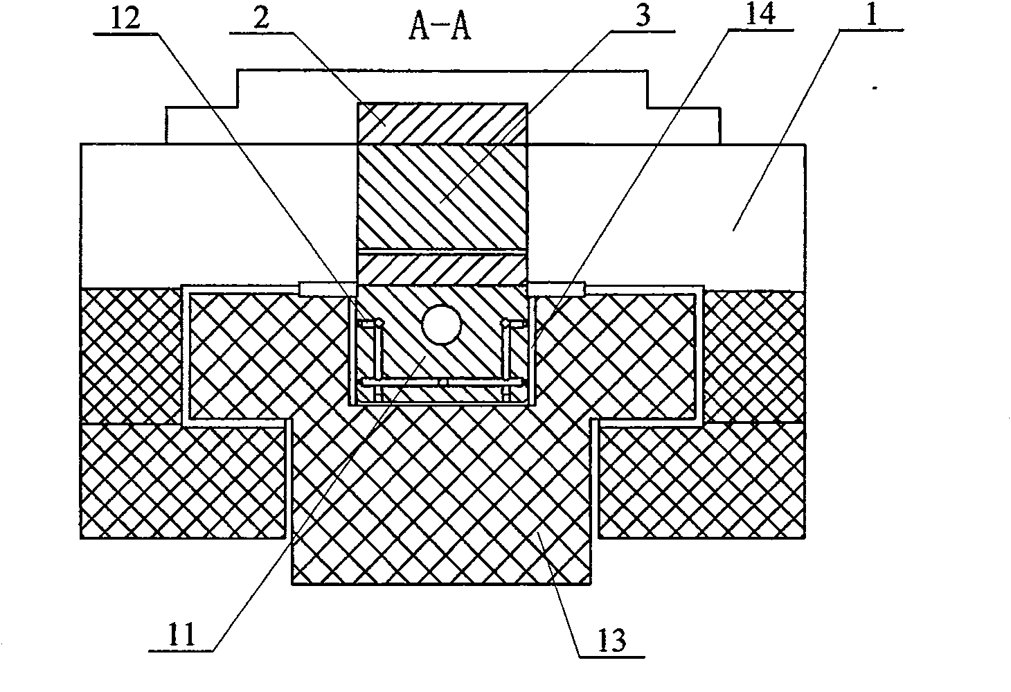
[0006] Specific implementation methods: (see figure 1 , figure 2 ) This embodiment consists of a slide plate 1, a connecting plate 2, a front push plate 3, a rear push plate 4, an intermediate push plate 5, a ball screw 9, a ball screw nut 10, an air flotation conversion block 11, a guide rail 13, and a front bracket 16 , a rear bracket 17, a motor 18 and a tailgate 19, the tailgate 19 is fixed on the rear end surface of the guide rail 13, the motor 18 is fixed on the tailgate 19, the slide plate 1 is arranged on the upper side of the guide rail 13, and the air float The conversion block 11 is arranged in the chute 14 of the guide rail 13, the front bracket 16 is arranged at the front part in the guide rail 13, the rear bracket 17 is arranged at the rear part in the guide rail 13, and the two ends of the ball screw nut 10 are connected with the front bracket 16 and the front bracket 13 respectively. The rear bracket 17 is connected, the middle section of the ball screw nut 1...


PUM


Abstract

An ultra-precise driving mechanism relates to a driving mechanism. The object of the present invention is to solve the problems of low static and dynamic rigidity and poor ability to resist external interference of the existing linear motion ultra-precision workbench. The upper part of the middle push plate of the present invention is arranged between the front push plate and the rear push plate, the lower end of the middle push plate is connected with the upper end of the air-flotation conversion block, the first throttling hole is arranged in the front push plate, and the rear push plate There is a second throttling hole inside, the first gas static pressure air film cavity is formed between the middle push plate and the front push plate, and the second gas static pressure air film cavity is formed between the middle push plate and the rear push plate. The conversion block is provided with static pressure throttling holes. The invention has the advantages of simple structure, reliable operation, and complete elimination of force interference in two directions other than the driving direction of the lead screw. High precision, the straightness of the large stroke ultra-precision table reaches 0.17μm / 600mm. High bearing capacity and wide application range, it can be applied to the drive of various forms of ultra-precision workbenches.

Description

technical field [0001] The invention relates to a driving mechanism. Background technique [0002] With the development of science and technology, the requirements for the manufacturing precision of product parts are getting higher and higher, and the key technology and related technologies of ultra-precision machining are urgently needed, especially ultra-precision machining machine tools, which are the core and key to realize ultra-precision machining of parts. In ultra-precision machining machine tools, hydrostatic and gas static pressure guide rails are widely used. Their biggest advantage is that the linear motion precision of the machine tool is high, which can reach submicron or even nanometer level, but their disadvantage is that their static and dynamic The rigidity is low, and the ability to resist external interference is poor. Therefore, when the driving system of the guide rail acts on the guide rail or the slide plate, the force interference will have a great ...

Claims


Application Information

Patent Timeline
Patent Type & Authority Patents(China)
IPC IPC(8): B23Q5/00B23Q5/34
Inventor 梁迎春张龙江张飞虎张景和许乔
Owner HARBIN INST OF TECH
Learn More