Cleaning apparatus

A cleaning device and cleaning liquid technology, which are applied in the directions of cleaning flexible articles, cleaning methods and utensils, cleaning methods using liquids, etc., can solve problems such as inability to use semiconductor process lithography technology, etc., and achieve suppression of precision reduction and environmental pollution. , to avoid the effect of increasing costs

Active Publication Date: 2009-12-09
SANYO ELECTRIC CO LTD +2
View PDF4 Cites 1 Cited by
  • Summary
  • Abstract
  • Description
  • Claims
  • Application Information

AI Technical Summary

Problems solved by technology

Therefore, the lithography technology of the semiconductor process cannot be used

Method used


Image

  • Cleaning apparatus
  • Cleaning apparatus
  • Cleaning apparatus

Examples


Embodiment Construction

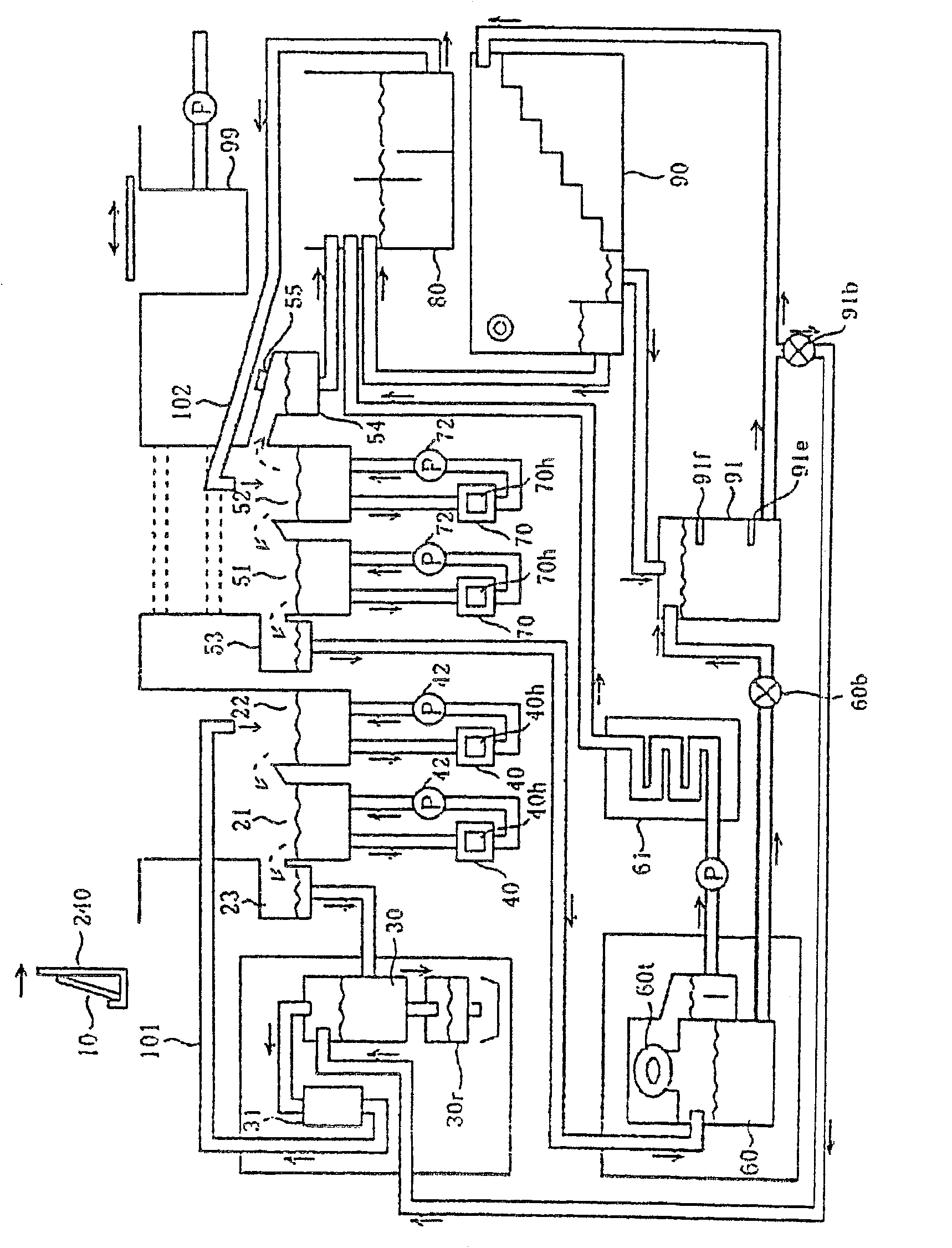
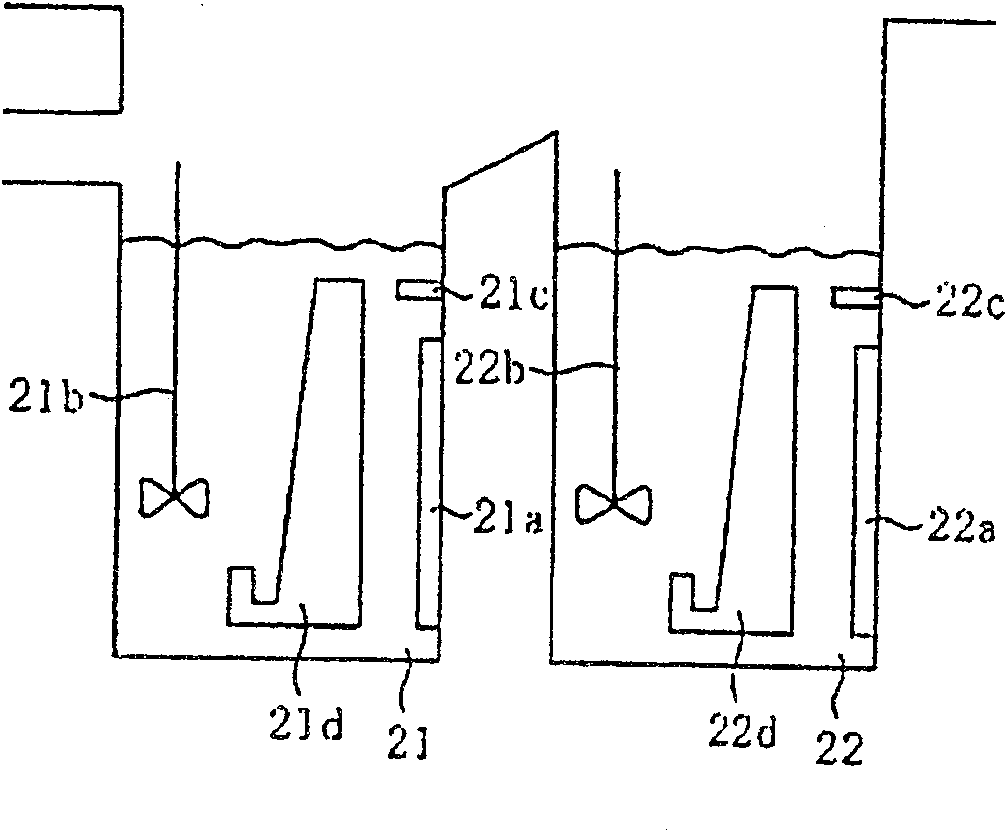
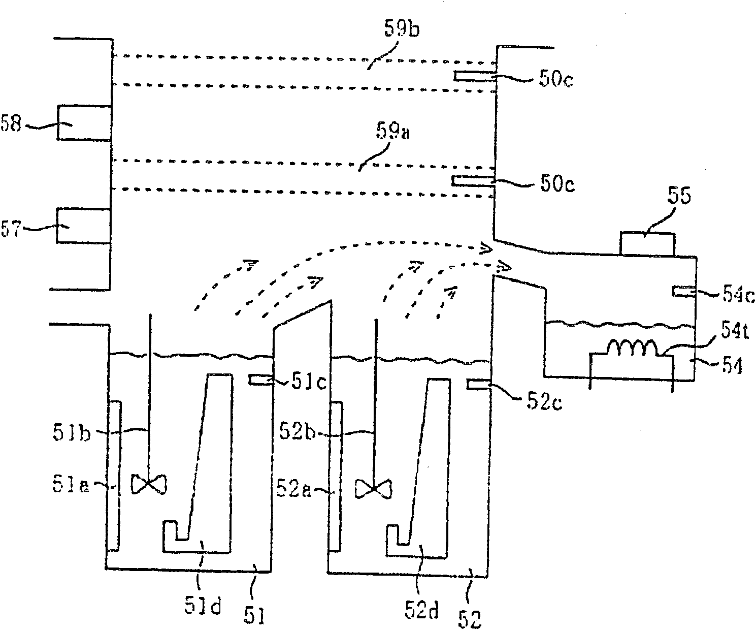
[0071] Next, a cleaning device according to an embodiment of the present invention will be described. The mask as the object to be cleaned is the same as in the Figure 15 to Figure 17 The same mask 10 used in the conventional evaporation step is shown. That is, the mask is composed of a metal thin film in which holes 11 of approximately several microns in length and width are formed along a predetermined pattern for forming an organic material. The metal thin film is made of, for example, nickel (Ni) and iron (Fe). In addition, a metal frame 12 made of nickel (Ni) and iron (Fe) is fixed to the edge of the mask. The metal frame 12 has a locking portion 13 . Hereinafter, the mask 10 fixed to the metal frame 12 is simply referred to as "mask 10".

[0072] The cleaning device of this embodiment is to remove the mask 10 attached to the metal thin film for vapor deposition in the vapor deposition step of vapor-depositing the organic material for organic EL on the insulating subs...


PUM


Abstract

A cleaning device capable of removing organic materials adhering to a mask made of a metal thin film. The cleaning device of the present invention has: the first and the second cleaning tanks (21, 22) for cleaning the mask (10) by a predetermined cleaning solution; Distiller (30); the first cooler (31) that cools the cleaning solution of vacuum distillation to room temperature; the cleaning solution cooled by the first cooler (31) is returned to the first cleaning tank (22) Return pipe (101); the first and second washing tanks (51, 52) for washing the mask (10) with a predetermined washing liquid; distilling the washing liquid of the washing tanks (51, 52) under normal pressure Atmospheric distiller (60); the 2nd cooler (61) that the rinsing liquid of atmospheric distillation is cooled to room temperature; Make the rinsing liquid cooled by the 2nd cooler (61) return to the 2nd rinsing tank (52 ) of the second return pipe (102).

Description

technical field [0001] The present invention relates to a cleaning device, and more particularly to a cleaning device for removing organic material adhering to a mask made of a metal thin film in a vapor deposition step of an organic material for organic EL. Background technique [0002] In recent years, organic EL display devices using organic electroluminescent (Electro Luminescence: hereinafter referred to as "organic EL") components have replaced CRT and LCD display devices and have been attracting attention. An organic EL display device of a thin film transistor (Thin Film Transistor: hereinafter referred to as "TFT") of an EL device. [0003] The organic EL components are sequentially stacked to form: the anode formed by transparent electrodes such as ITO (Indium Tin Oxide) and the like; the anode formed by MTDATA (4,4-bis(3-methylphenylaniline) A hole-transporting layer composed of a first hole-transporting layer such as TPD (4,4,4-tris(3-methylphenylanilino)tripheny...

Claims


Application Information

Patent Timeline
Patent Type & Authority Patents(China)
IPC IPC(8): C23C14/22C23C14/12
CPCB01D3/10B08B3/08B08B11/02B01D3/00B08B3/06B08B3/14
Inventor 木野村芳孝平冈照雄大川光治郎
Owner SANYO ELECTRIC CO LTD
Why Eureka
Try Eureka