Uninterruptible power supply

A technology of power supply and DC power supply, which is applied in the direction of current collectors, electric vehicles, electrical components, etc., and can solve problems such as low utilization rate of inductance, out-of-control fluctuation of bus capacitor voltage, and large filter volume, so as to prevent unbalanced bus voltage and reduce Bus voltage ripple, effect of reducing filter volume

Active Publication Date: 2010-01-06
EMERSON NETWORK POWER CO LTD
View PDF3 Cites 0 Cited by
  • Summary
  • Abstract
  • Description
  • Claims
  • Application Information

AI Technical Summary

Problems solved by technology

[0003] The disadvantage of this uninterruptible power supply is that two sets of batteries and two sets of inductors need to be set, which will lead to a substantial increase in the overall cost of the UPS
Because the inductor L1 works in the positive phase and does not work in the negative phase; the inductor L2 works in the negative phase and does not work in the positive phase, and the utilization rate of the inductor is low
When the output power of the UPS is high, several tubes Q1 and Q2 need to be used in parallel, because the switching time and characteristics of the power tubes cannot be completely consistent, and the power tubes cannot achieve good current sharing, which may reduce the overall system performance. reliability
In a 220V AC output system, the bus voltage needs to be increased to about ±400V, and the inverter module of the half-bridge inverter topology is used. The power switch tubes Q3 and Q4 need to use tubes with a withstand voltage of 1200V, and the tubes with a withstand voltage of 1200V are expensive; The switching frequency behind the 1200V withstand voltage tube should not be too high, the filter volume is large, and the cost is high; in addition, the inverter module adopts the half-bridge inverter topology, and the inverter module works in a two-level state, the voltage ripple is large, the filter volume is large, and the cost is high. High; the inverter module will charge the bus capacitor during the freewheeling period of the inductor L3, causing the voltage fluctuation on the bus capacitor to become larger or even out of control. Additional bus voltage balancing measures are required
For example: during normal phase operation: when Q3 is turned on, capacitor C1 charges inductor L3; when Q3 is turned off, inductor L3 discharges through C3, C2, and D4, and the discharge current will charge C2, while during normal phase operation, the bus capacitance C2 is uncontrolled, making the voltage on C2 fluctuate more

Method used


Image

  • Uninterruptible power supply
  • Uninterruptible power supply
  • Uninterruptible power supply

Examples


specific Embodiment approach 1

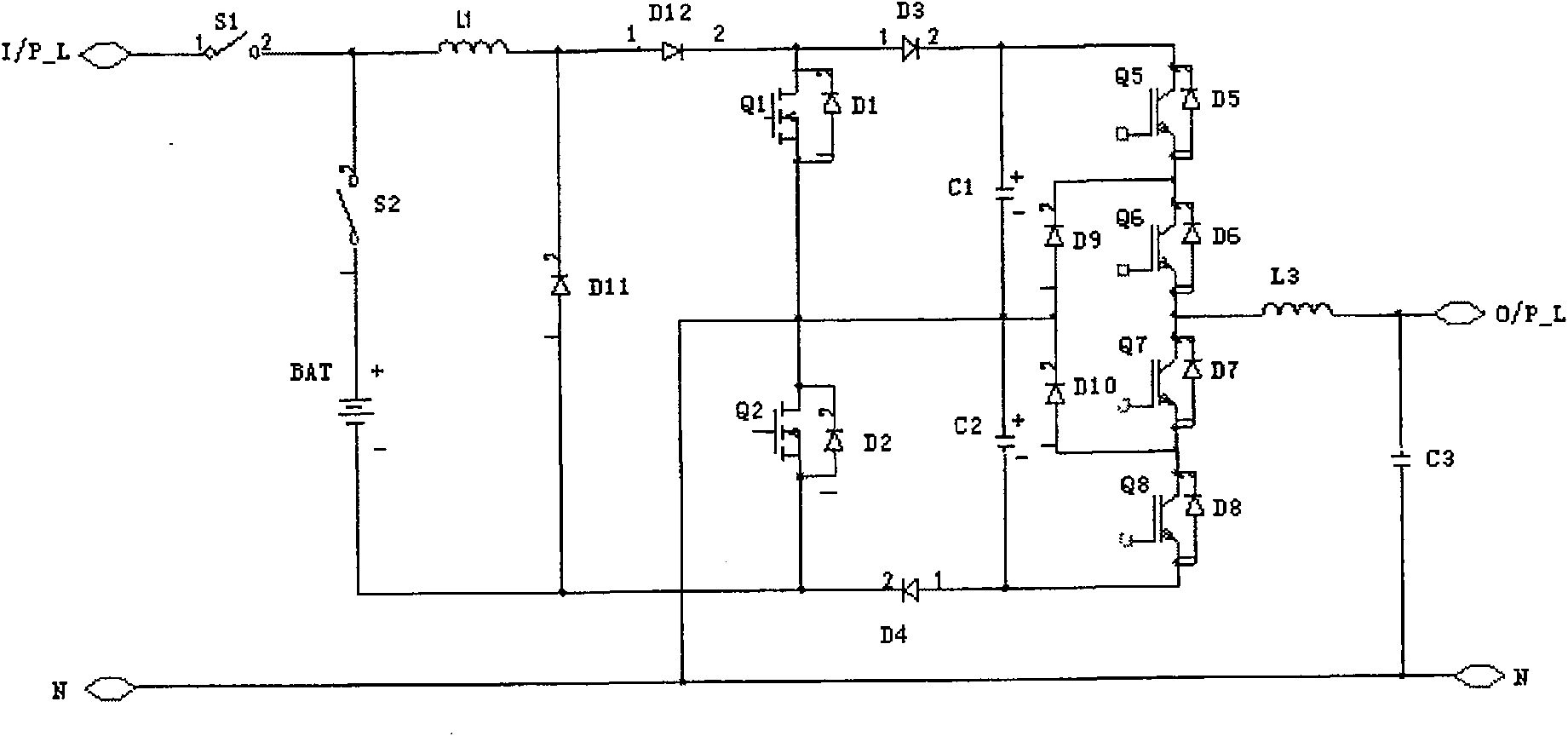
[0030] Such as figure 2 As shown, an uninterruptible power supply (UPS) includes an AC power input, a DC power supply, a controllable switch, a boost module and an inverter module, and the controllable switch is configured to selectively input AC power or The DC power supply is connected to the boost module, and the boost module is used to boost the AC power input or the input voltage provided by the DC power supply and output it to the inverter module, and the inverter module is used to output the boost module The voltage is converted into an AC voltage output. The DC power supply is composed of a group of batteries BAT, and the boost module includes an inductor L1, a first switching tube Q1, a second switching tube Q2, a first capacitor C1, a second capacitor C2, a rectifier tube D11, a twelfth Diode D12, third diode D3 and fourth diode D4. The rectifier is a diode. The twelfth diode D12 is used to prevent current from flowing through the first switch tube Q1 when the AC...

specific Embodiment approach 2

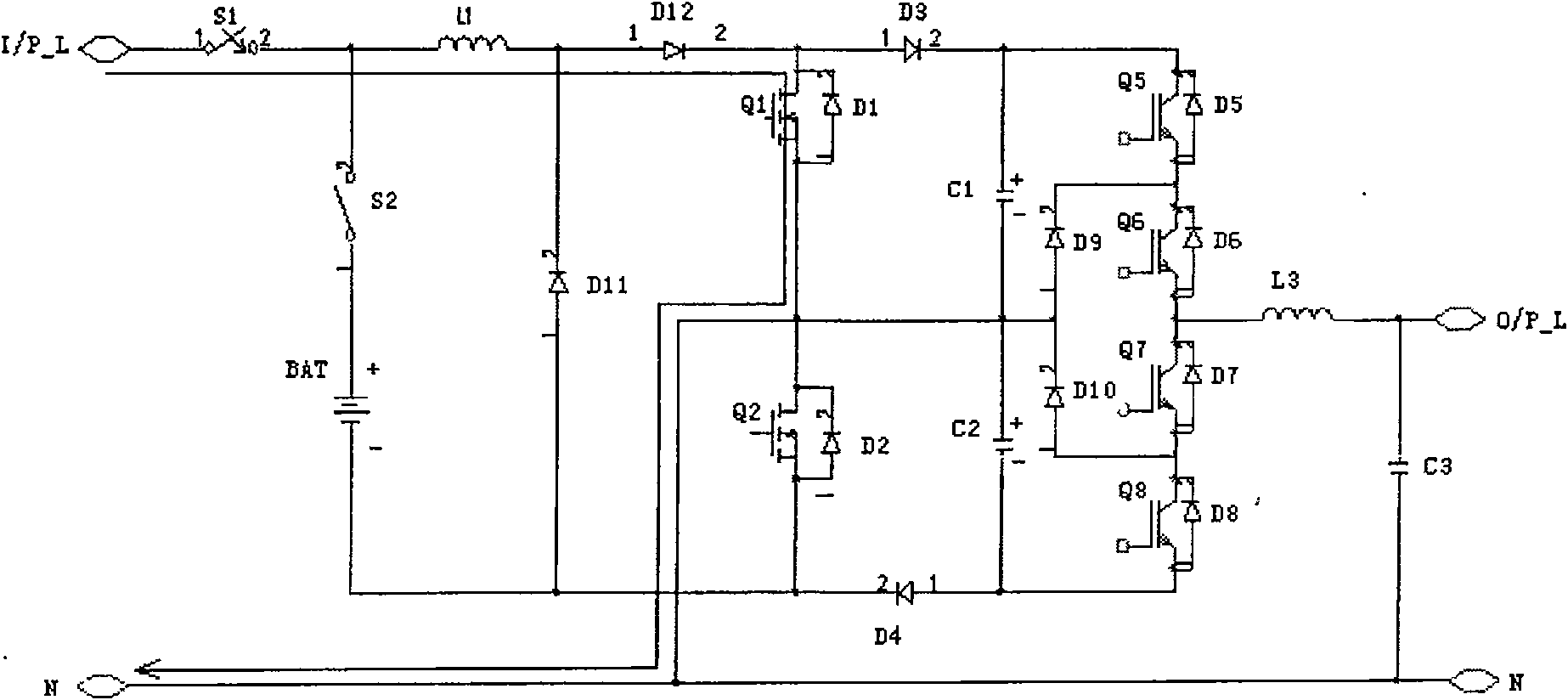
[0048] Such as Figure 11 As shown, the difference between this specific embodiment and the first specific embodiment is that the position of the twelfth diode D12 is changed. In this specific embodiment, the twelfth diode D12 is moved to the first switch tube Between the source of Q1 and the drain of the second switching transistor Q2. That is: the anode of the twelfth diode D12 is connected to the source of the first switching tube Q1, and the cathode of the twelfth diode D12 is connected to the drain of the second switching tube Q2 and the neutral line N of the AC power input. In this way, when the first switch tube Q1 is turned off and the third diode D3 is turned on, a diode loss can be saved.

specific Embodiment approach 3

[0049] Such as Figure 12 As shown, the difference between the present embodiment and the second embodiment is that the rectifier uses a power field effect transistor (MOS) with a body diode or an insulated gate bipolar transistor (Insulated Gate Bipolar Transistor, IGBT for short) with a body diode. ) instead. In the mains mode, the body diode D11 of the transistor Q11 is used as a rectifier diode; in the battery mode, the inductance L1 is charged and discharged by controlling the opening and closing of the Q11, and Figure 11 Compared with charging and discharging the inductor L1 by controlling the on-off of the first switching tube Q1 and the second switching tube Q2, the loss of another MOS tube can be saved.


PUM


Abstract

The invention discloses an uninterrupted power supply, which comprises an AC energy input, a DC power supply, a controllable switch, a boosting module and an inverter module, wherein the DC power supply consists of a battery pack; the boosting module includes an inductor, a first and a second switch tubes, a first and a second capacitors, a rectifying tube, a third and a fourth diodes, and a twelfth diode for preventing current from flowing through the first switch tube in negative phase AC state; the input terminal of the inductor is coupled with a live wire and the positive electrode of the DC power supply, and the output terminal is connected with the first terminal of the rectifying tube and coupled with the first terminal of the first switch tube; the third diode is connected with the first terminal of the first switch tube at the first terminal and connected with the negative electrode of the DC power supply through the first capacitor, the second capacitor and the fourth diode at the second terminal; a zero wire is coupled with the second terminal of the first switch tube and the first terminal of the second switch tube and connected between the first and the second capacitors; and the second switch tube as well as the second terminal of the rectifying tube is connected with the negative electrode of the DC power supply. The invention only needs one group of batteries and inductors which is at low cost.

Description

technical field [0001] The invention relates to an uninterruptible power supply. Background technique [0002] Such as figure 1 As shown, the existing uninterruptible power supply (UPS) generally includes AC power input, DC power supply, controllable switch, booster module and inverter module, and the controllable switch is configured to selectively input AC power or The DC power supply is connected to the boost module, and the boost module is used to boost the input voltage and output it to the inverter module, and the inverter module is used to convert the voltage output by the boost module into an AC voltage for output. The existing DC power supply includes two sets of batteries V1 and V2, which are respectively responsible for the positive phase and negative phase power supply in the battery mode. The boost module includes two sets of inductors L1, L2, two switch tubes Q1, Q2, two diodes D5, D6, and capacitors C1, C2. Most of the existing inverter modules adopt the ha...

Claims


Application Information

Patent Timeline
Patent Type & Authority Patents(China)
IPC IPC(8): H02J7/00
Inventor 余恒罗永昌
Owner EMERSON NETWORK POWER CO LTD
Why Eureka
Try Eureka