Output-less transistor UPS

A transformer without output technology, applied in the direction of output power conversion device, AC power input conversion to AC power output, circuit device, etc., can solve the problems of increasing the cost of the neutral line, poor cost performance, large switching loss, etc., to save construction Cost, reduction of loss and cost, effect of low bus voltage

Active Publication Date: 2007-07-18
VERTIV CORP
View PDF0 Cites 35 Cited by
  • Summary
  • Abstract
  • Description
  • Claims
  • Application Information

AI Technical Summary

Problems solved by technology

The disadvantage is that external input and output neutral lines are required
[0006] The UPS design without output transformer is suitable for grid systems with a neutral line and an output phase voltage of 220V, but for a grid system without a neutral line or with an output line voltage of 480V, if the same circuit is used directly, there are the following disadvantages: 1) Bus voltage Very high, generally 940V, need to use high withstand voltage IGBT devices and DC electrolytic capacitors, res...

Method used


Image

  • Output-less transistor UPS
  • Output-less transistor UPS
  • Output-less transistor UPS

Examples


specific Embodiment 1

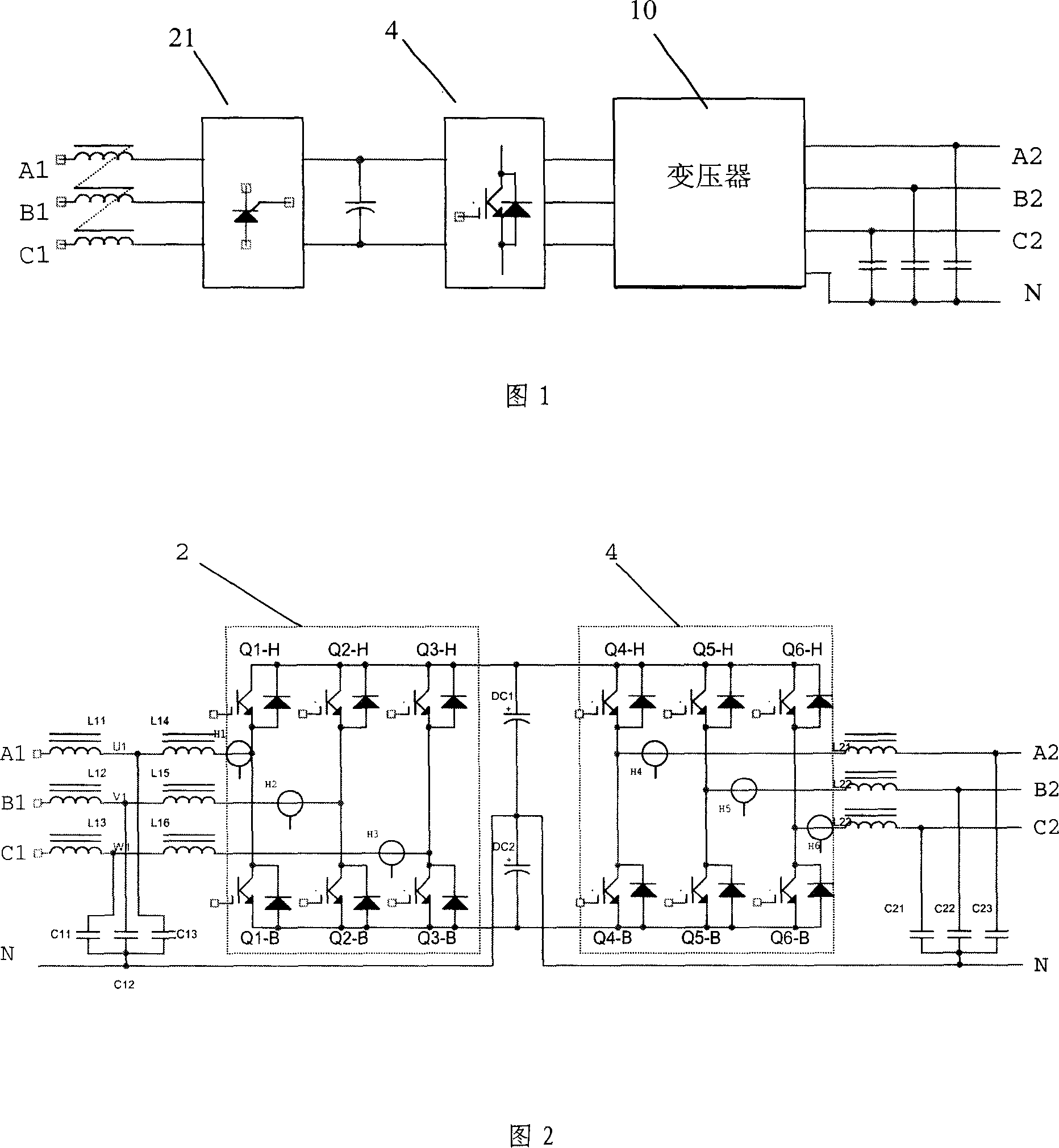
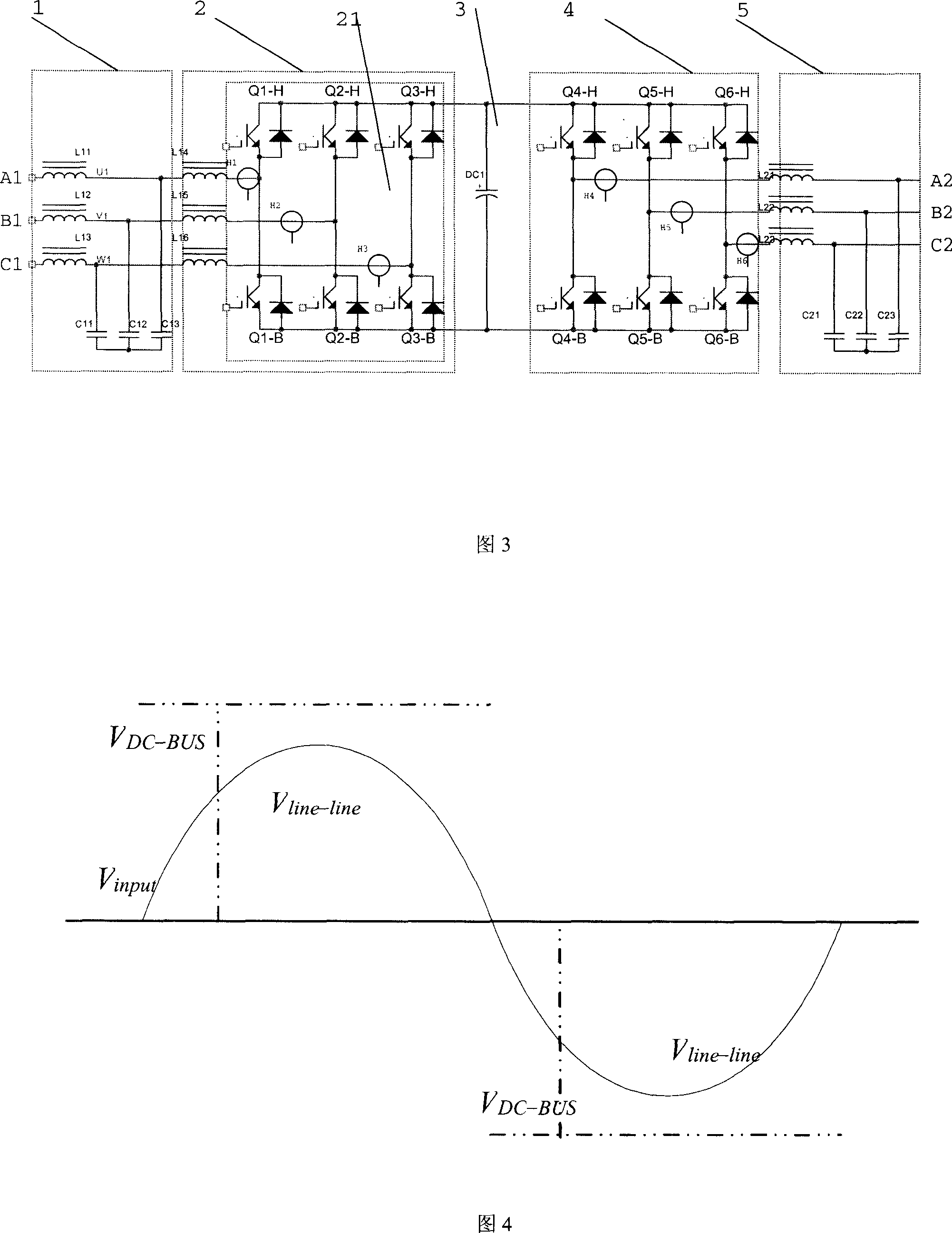
[0030] Specific Embodiment 1. As shown in FIG. 3 , there is no external input and output neutral line, and the input and output are three-phase three-wire system. The input circuit 1 only inputs the three-line voltage of the power-frequency three-phase alternating current, because there is no input neutral line, so there is no phase voltage. The input circuit 1 is preferably composed of input filter capacitors C11, C12, C13 and input filter inductors L11, L12, L13, which eliminates the influence of high-frequency switching ripple current on the power grid, and the input of input filter inductors L11, L12, L13 The terminals are respectively connected to the three-phase AC input terminals A1, B1, and C1, and one end of the input filter capacitors C11, C12, and C13 is respectively connected to the output ends of the input filter inductors L11, L12, and L13, and the other end of the input filter capacitors C11, C12, and C13 connected. The boost rectifier circuit 2 includes three ...

specific Embodiment 2

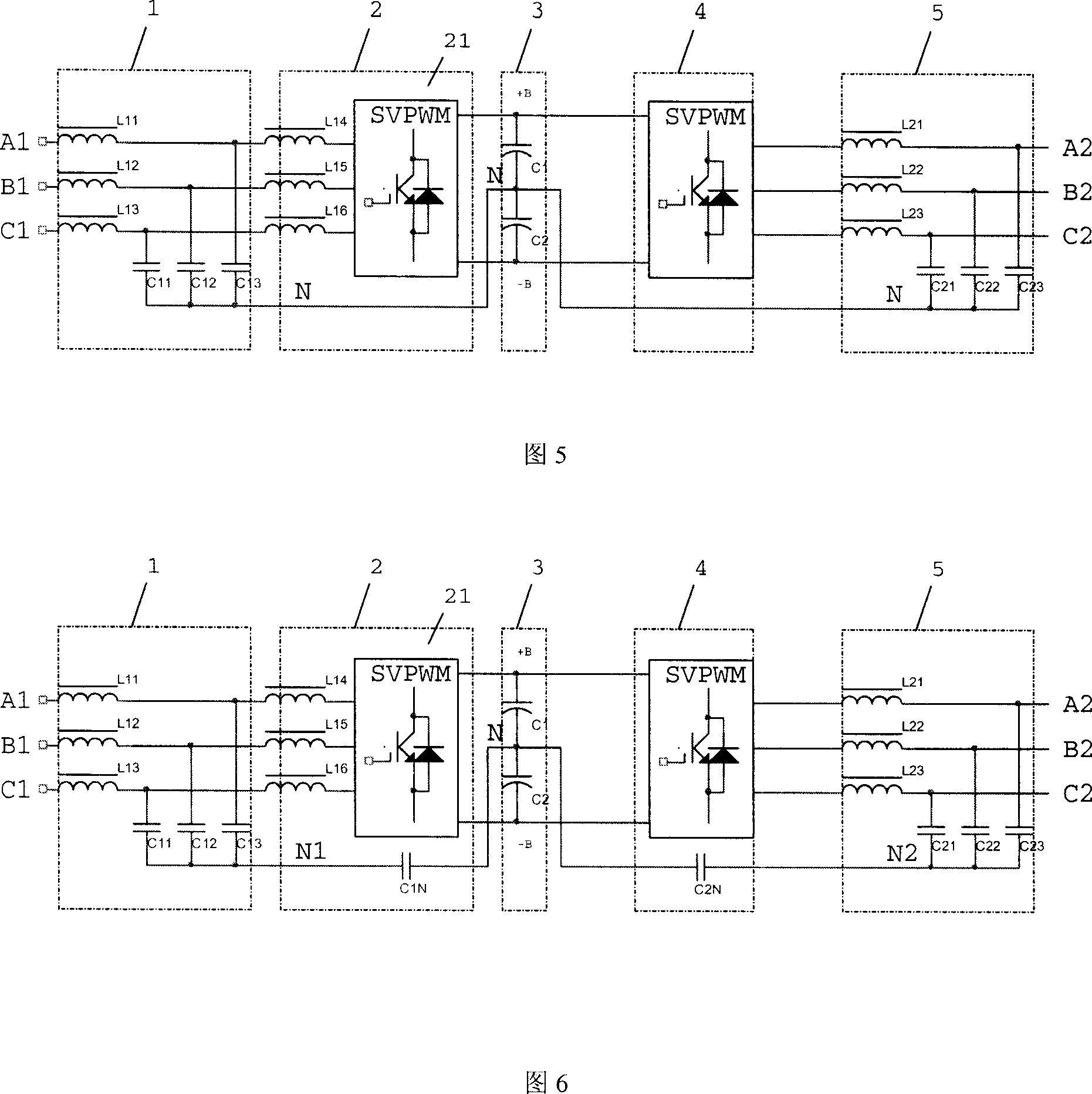
[0033] Specific Embodiment 2, as shown in FIG. 5 , the difference from Embodiment 1 is that an internal midline structure is added. The input live wire will generate a common-mode voltage to the ground, and the common-mode voltage will cause damage to the load. In order to avoid damage to the load by the common-mode voltage, a common-mode voltage release circuit is provided inside the UPS. The first capacitor C1 and the second capacitor C2 connected in series are connected between the positive and negative DC bus bars +B and -B, and the input filter capacitors C11, C12, C13 and output filter capacitors C21, C22, C23 are respectively connected with the first capacitor C1, the second capacitor The central point of the series connection of the two capacitors C2 constitutes an internal neutral line loop, providing a path for the common mode signal.

specific Embodiment 3

[0034] Specific embodiment three, as shown in Figure 6, differs from embodiment two in that the first neutral line filter capacitor C1N and the second neutral line filter capacitor C2N are connected in series in the neutral line circuit, wherein the first neutral line filter capacitor C1N is connected in series with the input filter Between the capacitors C11, C12, C13 and the central points of the first capacitor C1 and the second capacitor C2 connected in series, the second neutral line filter capacitor C2N is connected in series with the output filter capacitors C21, C22, C23 and the first capacitor C1 and the first capacitor connected in series respectively. between the center points of the second capacitor C2. In this embodiment, the current formed by the third harmonic can be blocked by the neutral line filter capacitors C1N and C2N, and only the high-frequency switching ripple is allowed to pass, so that the voltage drop on the input inductor and the current flowing on t...


PUM


Abstract

This invention discloses a UPS without any output transformer including an input circuit, a rectification circuit composed of switches and inputting industrial frequency AC power and finishing boosting and rectification function by the input circuit, a DC bus, an inverse circuit connected to the rectification circuit by the DC bus and inverting stable sine waves, an output circuit outputting the sine wave to the load, in which, it has no exterior input and output midline, the input terminal of the input circuit is composed of two or three phase line voltage input voltages and the output of the output circuit is also composed of two or three-phase line voltage terminals.

Description

【Technical field】 [0001] The invention relates to power supply technology, in particular to an uninterruptible power supply (UPS) without an output transformer. 【Background technique】 [0002] The current double-conversion UPS is usually of two types: with output transformer and with neutral without output transformer. [0003] The UPS with output transformer is shown in Figure 1: usually the rectifier 21 stabilizes the bus voltage to a lower voltage, which facilitates the direct connection of the battery to the bus, uses the rectifier as a battery charger, and then uses the inverter in the inverter 4 link The regulator 4 is combined with the transformer 10 to adjust the boost and stabilize the voltage. The advantage of this method is that it saves the high-power battery charging and discharging conversion, realizes electrical isolation, and has a low output zero-ground voltage. The disadvantage is that it must be equipped with a transformer, and the transformer ratio must...

Claims


Application Information

Patent Timeline
IPC IPC(8): H02M5/45H02J9/00
Inventor 肖学礼邴阳
Owner VERTIV CORP
Why Eureka
Try Eureka