Quasi-common path type feedback interferometer of laser in microchip

A microchip laser, laser technology, applied in lasers, laser parts, phonon exciters, etc., can solve the problems of system resolution, air refractive index fluctuation, feedback light drift, etc., which affect the actual displacement measurement, and achieve environmental resistance. Improved interference capability, high sensitivity, and the effect of eliminating dead-end errors

Inactive Publication Date: 2007-07-25
TSINGHUA UNIV
View PDF0 Cites 31 Cited by
  • Summary
  • Abstract
  • Description
  • Claims
  • Application Information

AI Technical Summary

Problems solved by technology

[0006] However, the common optical feedback phase measurement method cannot avoid the negative influence of the dead range error in the actual measurement
Since the entire feedback external cavity is a dead path, factors such as air refractive index fluctuations, component deformation caused by temperature changes, and the instability of the lase

Method used


Image

  • Quasi-common path type feedback interferometer of laser in microchip
  • Quasi-common path type feedback interferometer of laser in microchip
  • Quasi-common path type feedback interferometer of laser in microchip

Examples


Embodiment 2

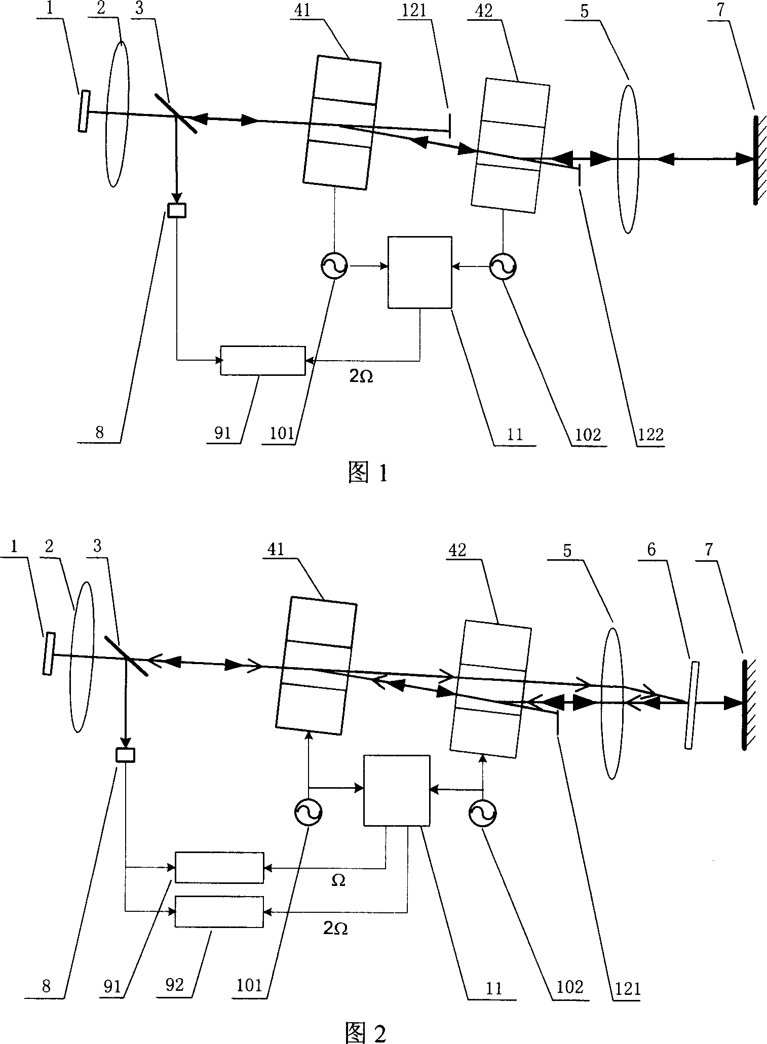
[0081] The difference between embodiment 2 and embodiment 1 is that embodiment 1 uses two acousto-optic frequency shifters for differential frequency shifting, which can achieve a lower frequency shifting frequency, which is conducive to improving the sensitivity of the system to feedback light; implementing Example 2 only uses an acousto-optic frequency shifter for frequency shifting. Its frequency shifting frequency is relatively high, and the sensitivity of the system is relatively low, but the system structure is simpler.

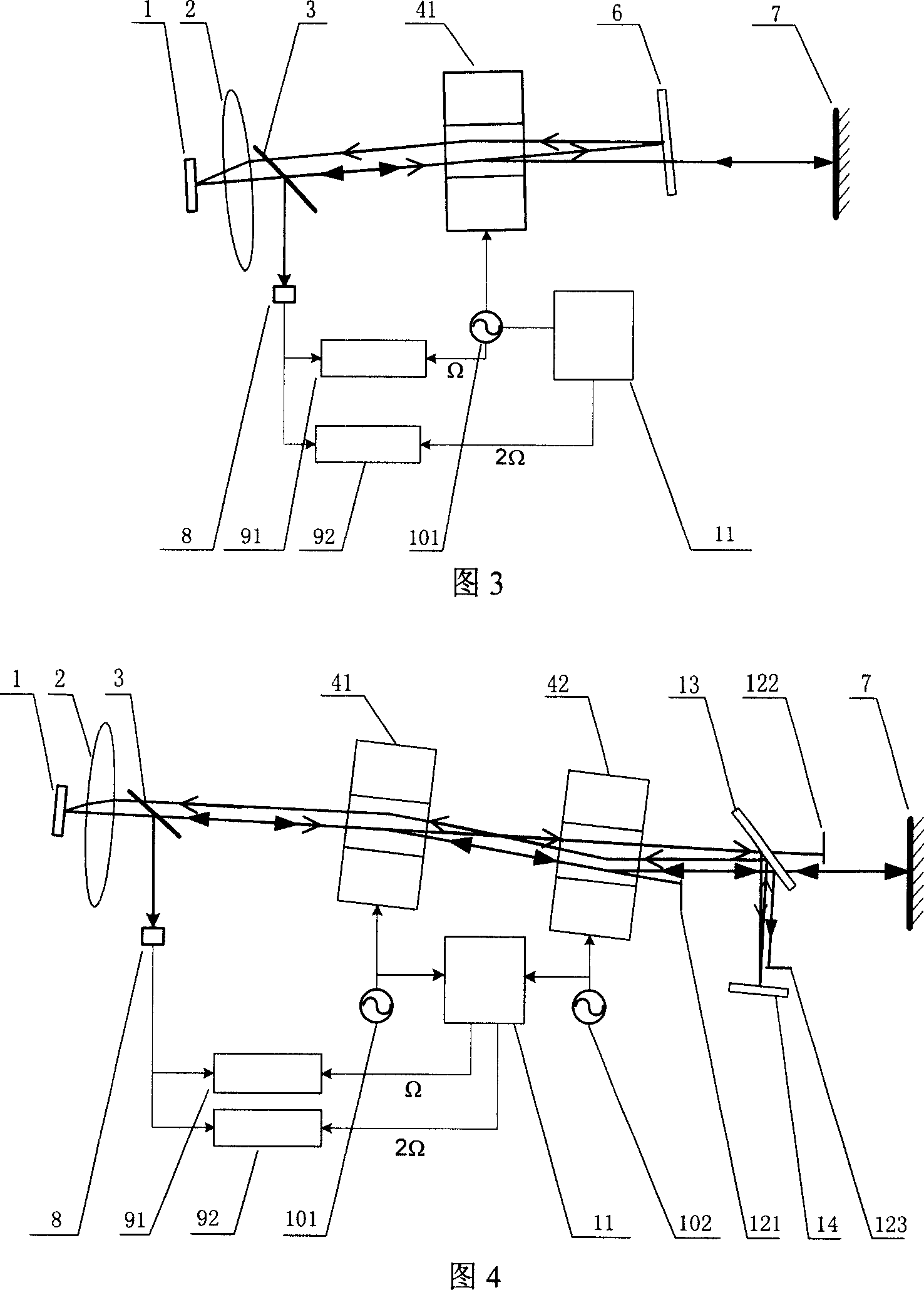
[0082] The structure of Embodiment 3 of the present invention is shown in Figure 4, including:

[0083] A microchip laser 1, a collimator lens 2 and a beam splitter 3 sequentially placed on the axis of the laser emitting end; a first acousto-optic frequency shifter 41 and a second acousto-optic frequency shifter 42 sequentially placed on the transmission light path of the beam splitter 3 , the first light blocking plate 121, the beam splitter 13; the se...

Embodiment 3

[0084] The difference between embodiment 3 and embodiment 1 is that: in embodiment 1, the external cavity optical paths of the measured feedback light and the reference feedback light cannot be absolutely equal; embodiment 3 uses a split optical path, which can be made by the position of the reference mirror The optical path of the reference feedback light and the measurement feedback light are equal, which can further reduce the phase drift caused by the frequency drift of the laser.


PUM


Abstract

A feedback interferometer of quasi-copath micro-plate laser consists of micro-plate laser; lens and beam splitter set on axle of emission end in sequence; two acousto-optic frequency shifters, light block plate, focusing lens and reference reflector set in sequence on transmission light path of beam splitter; photoelectric detector and two sine signal generators set on reflection light path of beam splitter; reference electric signal generating circuit and two orthogonal phase sensitive detectors.

Description

technical field [0001] The invention belongs to the technical field of precision displacement measurement, and is particularly suitable for non-contact precision displacement measurement of non-cooperating targets. Background technique [0002] Laser interferometer is the main tool for precision displacement measurement and length measurement at present; it uses laser wavelength as the benchmark of displacement or length measurement, and can be directly traced to the international standard of length measurement; through various phase subdivision technologies, laser interferometer can realize very High displacement measurement resolution. However, the laser interferometer needs a target mirror as a complex in the measurement process, and the target mirror is usually a tetrahedral mirror, which has a large volume. In many applications, the object to be tested is a non-complex, and the target mirror cannot be fixed on the object to be tested, for example, the displacement meas...

Claims


Application Information

Patent Timeline
IPC IPC(8): G01B9/02G01B11/00G01B11/02G01B11/16G02F2/02G02F1/35H01S3/00
Inventor 张书练万新军
Owner TSINGHUA UNIV
Why Eureka
Try Eureka