Low height lead frame for LED device and the manufacturing method thereof

A technology for LED devices and lead frames, which is applied in the field of lead frames for small-sized LED devices, and can solve problems such as resin cracks, epoxy resin leakage, lead frames and resin peeling, etc.

Inactive Publication Date: 2007-07-25
ENOMOTO
View PDF0 Cites 15 Cited by
  • Summary
  • Abstract
  • Description
  • Claims
  • Application Information

AI Technical Summary

Problems solved by technology

[0007] In the existing LED devices, in order to reduce the height, the thickness of the resin part under the lead frame is reduced, and the length of the root parts 12c and 12e corresponding to the external lead part is also tried to be shortened. When the bending stress applied to the lead frame is too large , it is easy to cause problems such as peeling between the lead frame and the resin, or cracks on the resin
Therefore, the epoxy resin for sealing easily leaks to the outside through the peeled part and the cracked part, which becomes a defect of the LED device.

Method used


Image

  • Low height lead frame for LED device and the manufacturing method thereof
  • Low height lead frame for LED device and the manufacturing method thereof
  • Low height lead frame for LED device and the manufacturing method thereof

Examples


Embodiment Construction

[0049] Hereinafter, a lead frame for a small-sized LED device according to an embodiment of the present invention will be described in detail with reference to the attached drawings.

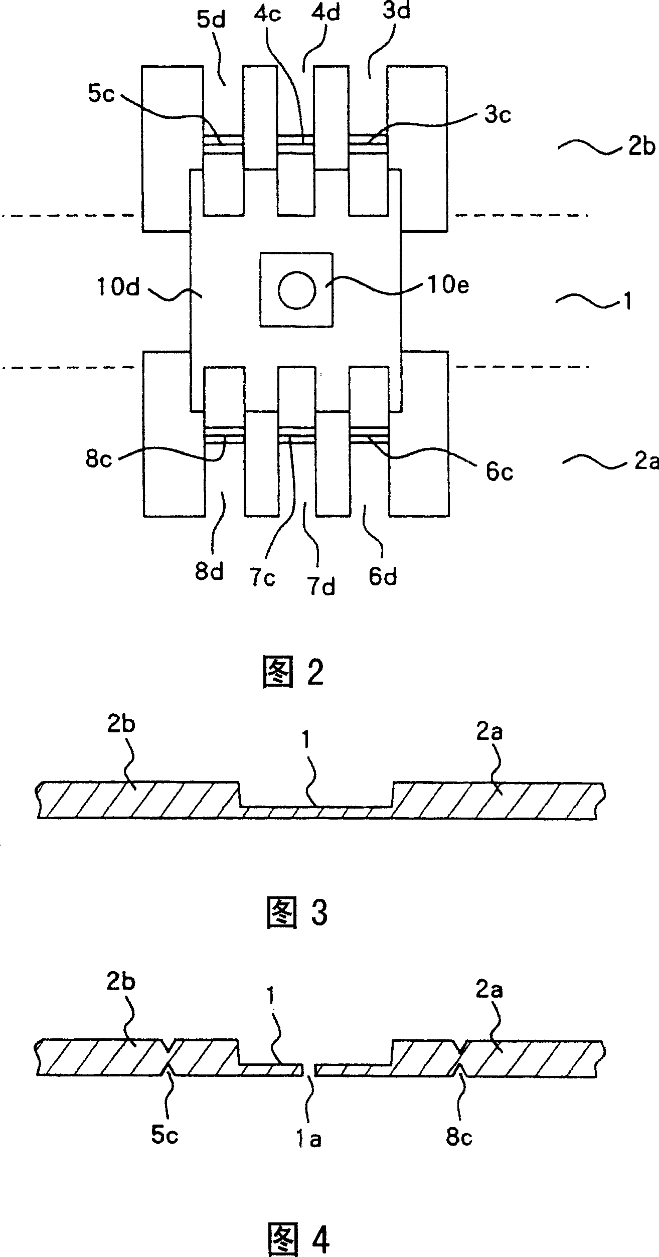
[0050] 3 is a cross-sectional view of a long irregular-shaped metal material used to manufacture a lead frame for a small-sized LED device according to an embodiment of the present invention, and is a cross-sectional view perpendicular to the longitudinal direction.

[0051] Both sides of the thin part 1 with a thickness of about 0.15 to 0.25 mm are sandwiched by normal parts 2a and 2b with a thickness of about 0.4 to 0.5 mm in parallel. Considering the electrical conductivity and price, copper alloy and stainless steel can be used as the material.

[0052] Fig. 4 is a cross-sectional view of a state in which a V-shaped groove is formed by drilling the long irregular-shaped metal material shown in Fig. 3 through a multi-station press (multi-stage sequential transfer press group). The drilled po...


PUM


Abstract

Provided is a small size LED apparatus which will not easily cause separation between the lead frame and the resin and resin crack, and has a height lower than 1 mm. In addition, a manufacturing method for the small size LED apparatus is also provided. The small size LED apparatus uses the lead frame to drill the long and abnormal metal material which arranged in order with common part, thin wall part and common part in longer direction with a thickness rate of 2.5:1-3.5:1, forms a chip pad part and an inner wire part on the thin wall part, forms an external wire part on the common part, and jets a formed resin cup shape part, and cuts off the external wire part to form the end part for the external wire part and will not bend the external wire part.

Description

technical field [0001] The invention relates to a lead frame for small-sized LED devices used for manufacturing small-sized LED (light emitting diode) devices. In addition, it also relates to a manufacturing method of a lead frame for a small-sized LED device. Background technique [0002] Fig. 7 is a front sectional view of a conventional LED device. [0003] The long plate-shaped metal material with uniform thickness is subjected to multi-stage press processing by a multi-station press, and then passed through an injection molding machine to perform resin molding on the chip pad part and the inner lead part 12a, 12b to form a resin cup-shaped part. Next, the outer lead parts 12c, 12d, 12e, and 12f are bent at 90 degrees at two positions to form a "U" shape, and the front ends 12d and 12f of the outer lead parts are brought into close contact with the bottom surface 10d of the resin cup. The root portions 12c and 12e of the outer lead portion are set parallel to the side ...

Claims


Application Information

Patent Timeline
Patent Type & Authority Applications(China)
IPC IPC(8): H01L33/00H01L23/495H01L21/48H01L33/60H01L33/62
CPCH01L2924/0002
Inventor 梅屋一芳
Owner ENOMOTO
Why Eureka
Try Eureka