High-frequency pulse pinking engine and control method thereof

A detonation engine and high-frequency pulse technology, which is applied to machines/engines, rocket engine devices, mechanical equipment, etc., can solve the problems of cycle efficiency and exhaust noise that are difficult to improve, and achieve the effect of reducing exhaust noise.

Inactive Publication Date: 2007-08-08
NORTHWESTERN POLYTECHNICAL UNIV
View PDF0 Cites 28 Cited by
  • Summary
  • Abstract
  • Description
  • Claims
  • Application Information

AI Technical Summary

Problems solved by technology

[0007] In order to solve the shortcomings of existing pulse detonation engines that rely heavily on high-power pulse ignition units and independent isolation gas systems, and that the cycle efficiency and exha

Method used


Image

  • High-frequency pulse pinking engine and control method thereof
  • High-frequency pulse pinking engine and control method thereof
  • High-frequency pulse pinking engine and control method thereof

Examples


Embodiment 1

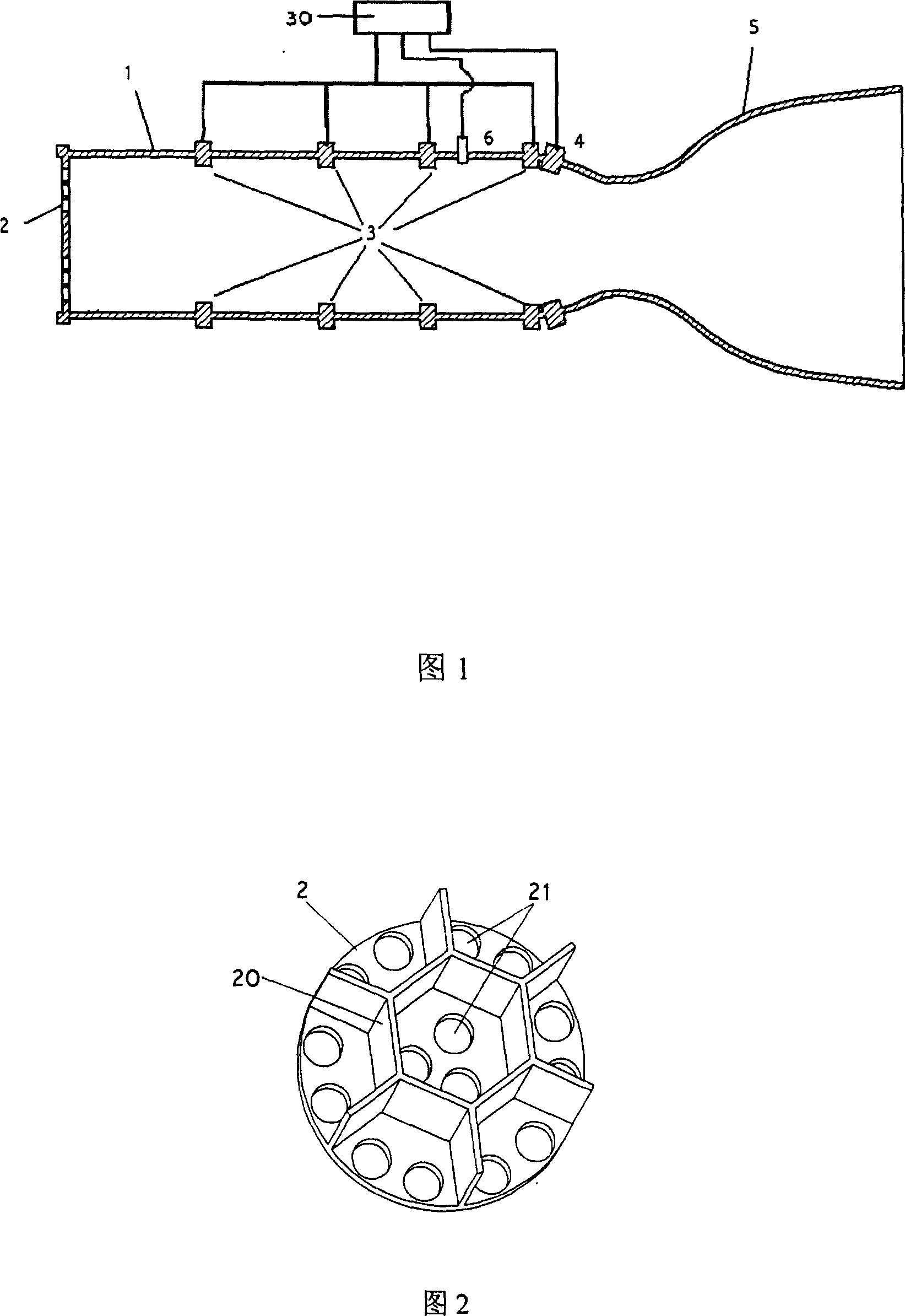
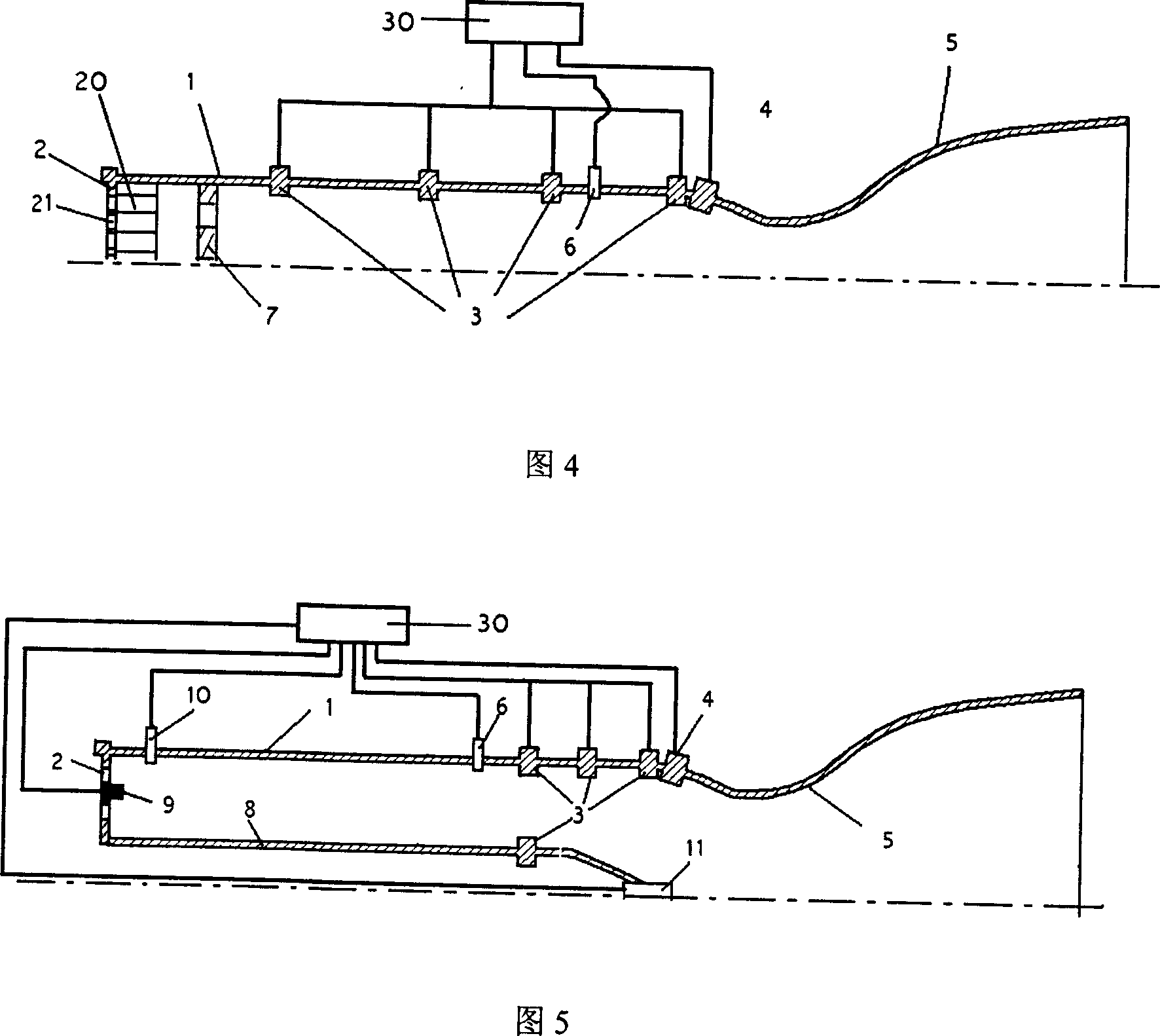
[0035] Embodiment 1, as shown in FIG. 4 , includes a pulse detonation engine combustion chamber housing 1 with an inner diameter of 100 mm and a length of 500 mm. Main propellant injection panel 2, secondary propellant nozzle 3, detonation auxiliary nozzle 4, nozzle 5, perforated plate 7, rectifier 20, control unit 30 and rear sensor 6, one end of the combustion chamber shell 1 is connected to the main propellant Injection panel 2, the other end is connected with nozzle 5; a rectifier 20 is fixedly connected on the main propellant injection panel 2, each channel of the rectifier 20 corresponds to a main propellant injection on the main propellant injection panel 2 Hole 21, the length of the rectification channel is 20mm. A perforated plate 7 is installed on the main propellant injection panel 2 and 100mm downstream. The clogging ratio of the perforated plate 7 is 0.4, and the Ф3 small holes are evenly distributed. 24 secondary propellant nozzles 3 are evenly distributed in si...

Embodiment 2

[0037] Embodiment 2, as shown in Figure 5, includes a pulse detonation engine combustion chamber housing 1, a main propellant injection panel 2, a secondary propellant nozzle 3, an auxiliary detonation nozzle 4, a nozzle 5, a rear sensor 6, a head Secondary propellant nozzle 9 , igniter 11 , control unit 30 and combustion chamber casing 8 . Combustion chamber shell 1 internal diameter 150mm, long 500mm, and combustion chamber shell external diameter 75mm, long 500mm. One end of the combustion chamber housing 1 is connected to the main propellant injection panel 2, and the other end is connected to the nozzle 5; the secondary propellant nozzles 3 are evenly distributed on the rear section of the combustion chamber housing 1 and the combustion chamber housing 8, and the detonation assists The nozzle 4 is located downstream of all secondary propellant nozzles 3 and before the nozzle throat; there is also a rear sensor 6 on the combustion chamber casing 1, which is located 100mm u...


PUM

PropertyMeasurementUnit
The inside diameter ofaaaaaaaaaa
Outer diameteraaaaaaaaaa

Abstract

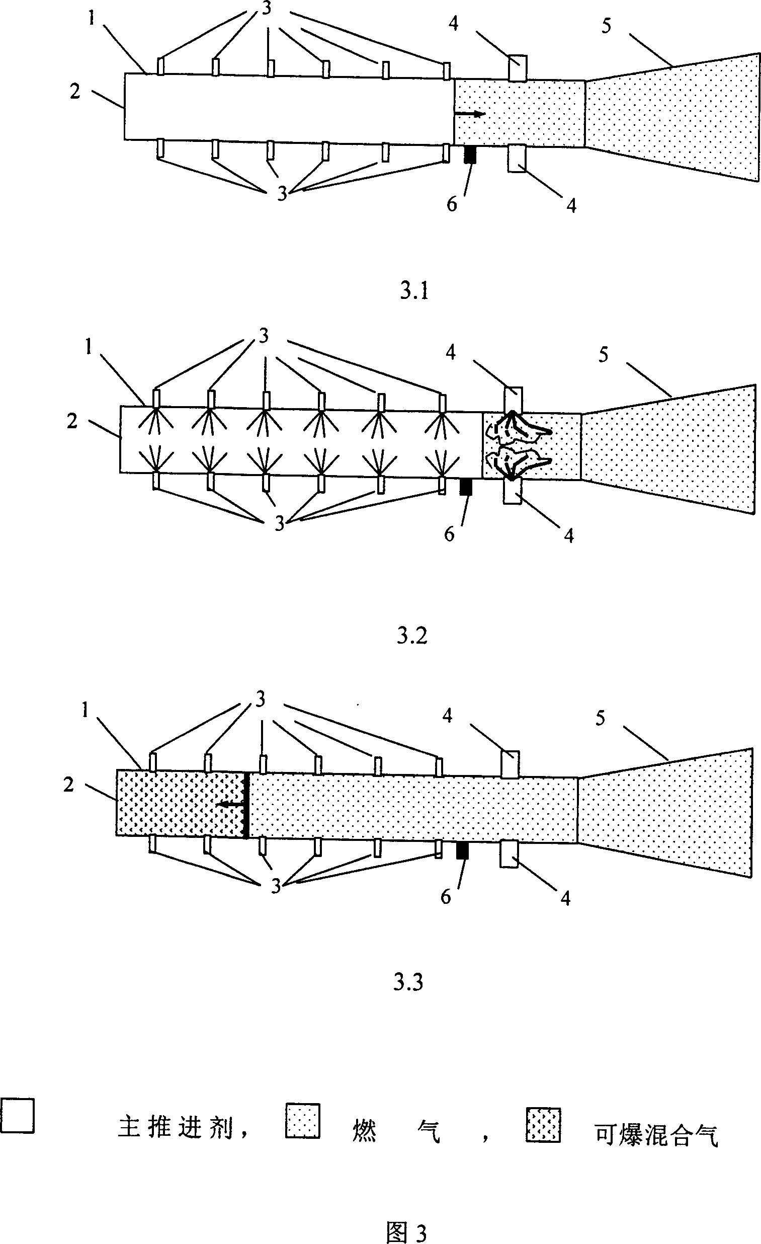
The invention relates to a pulse detonation engine with high frequency and the control method. The engine comprises combustor shell 1, jet panel of main propellant 2, nozzle of side secondary propellant 3, detonation assistant nozzle 4, jet pipe 5, post sensor 6 and control cell 30. The main propellant can be jetted out from the jet panel of main propellant 2 in high pressure and high speed. When the interface of main propellant and high-temperature fired gas spreads to the downstream of combustor, the secondary propellant is jetted in from the nozzle 3 and hypersensitivity detonation mixed gas is jetted from the detonation assistant nozzle 4 to detonate; the detonation wave is formed upwards to spread and then the high-temperature gas in combustor expands outward rapidly; when the pressure in combustor is decreased to the jetting total pressure of main propellant, the main propellant is jetted again. According to it the invention obtains the pulse detonation engine with very high working frequency and full development for detonation wave, which does not depend on the pulse firing system with high energy and high frequency and the isolating gas system. The gas drainage noise can be decreased in a large scale.

Description

(1) Technical field [0001] The invention relates to the technical field of engines, in particular to a detonation engine and a control method thereof. (2) Background technology [0002] There are two kinds of combustion waves in nature: one is deflagration wave and the other is detonation wave. The detonation wave propagates toward the unburned mixture at a speed of several kilometers per second. A detonation wave is essentially a shock wave followed by a combustion wave. The detonation wave can generate extremely high gas pressure (greater than 15 to 55 atmospheres) and gas temperature (greater than 2800K). Due to the extremely fast propagation speed of the detonation wave, the subsequent combustion process can be regarded as a constant volume combustion process, so its combustion efficiency very high. Due to the high efficiency of the pulse detonation cycle, and the pulse mode of operation, this makes it very attractive for propulsion systems. When the working frequenc...

Claims


Application Information

Patent Timeline
IPC IPC(8): F02K9/42F02K9/56
Inventor 李牧严传俊范玮
Owner NORTHWESTERN POLYTECHNICAL UNIV
Why Eureka
Try Eureka