Self-adaptive optical system based on linear phase inversion restoration technology

A technology of adaptive optics and linear phase, applied in the field of optics, it can solve the problems of complex algorithm and large amount of calculation.

Inactive Publication Date: 2007-08-08
INST OF OPTICS & ELECTRONICS - CHINESE ACAD OF SCI
View PDF0 Cites 34 Cited by
  • Summary
  • Abstract
  • Description
  • Claims
  • Application Information

AI Technical Summary

Problems solved by technology

However, the usual phase inversion technology compares the difference between two or more images before focus, at the focal plane or after focus, and obtains the corresponding wavefront phase information through an iterative algorithm. The algorithm i

Method used


Image

  • Self-adaptive optical system based on linear phase inversion restoration technology
  • Self-adaptive optical system based on linear phase inversion restoration technology
  • Self-adaptive optical system based on linear phase inversion restoration technology

Examples


Embodiment Construction

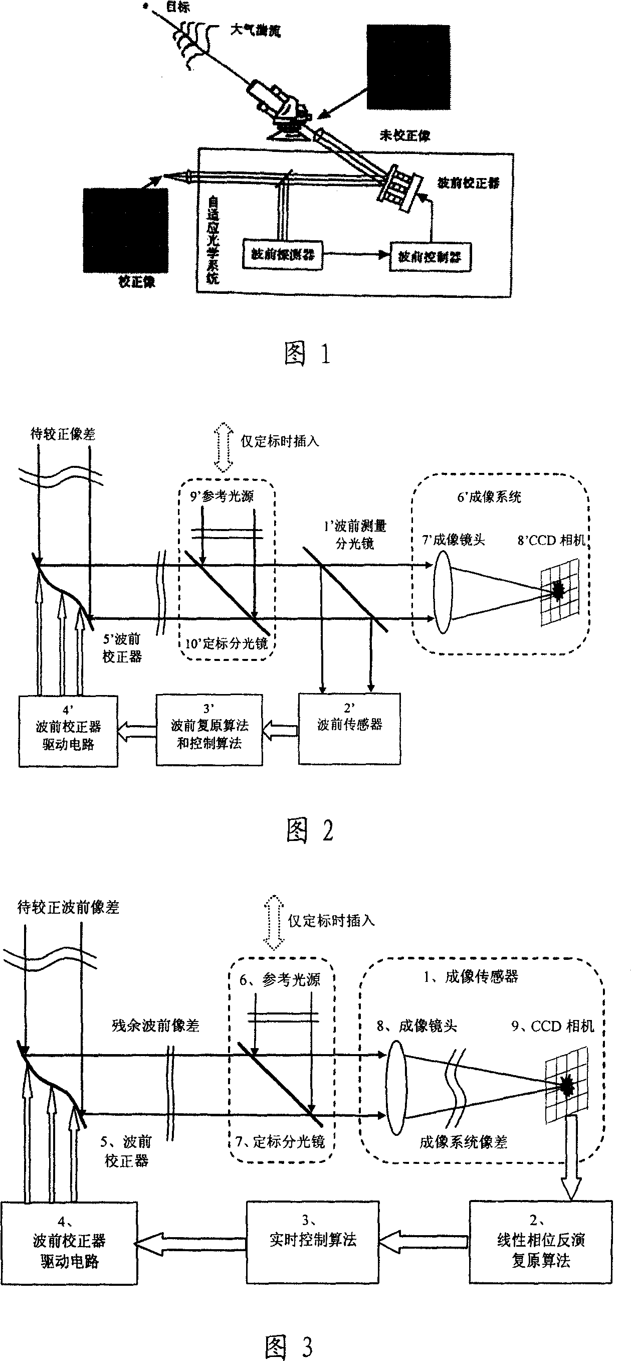
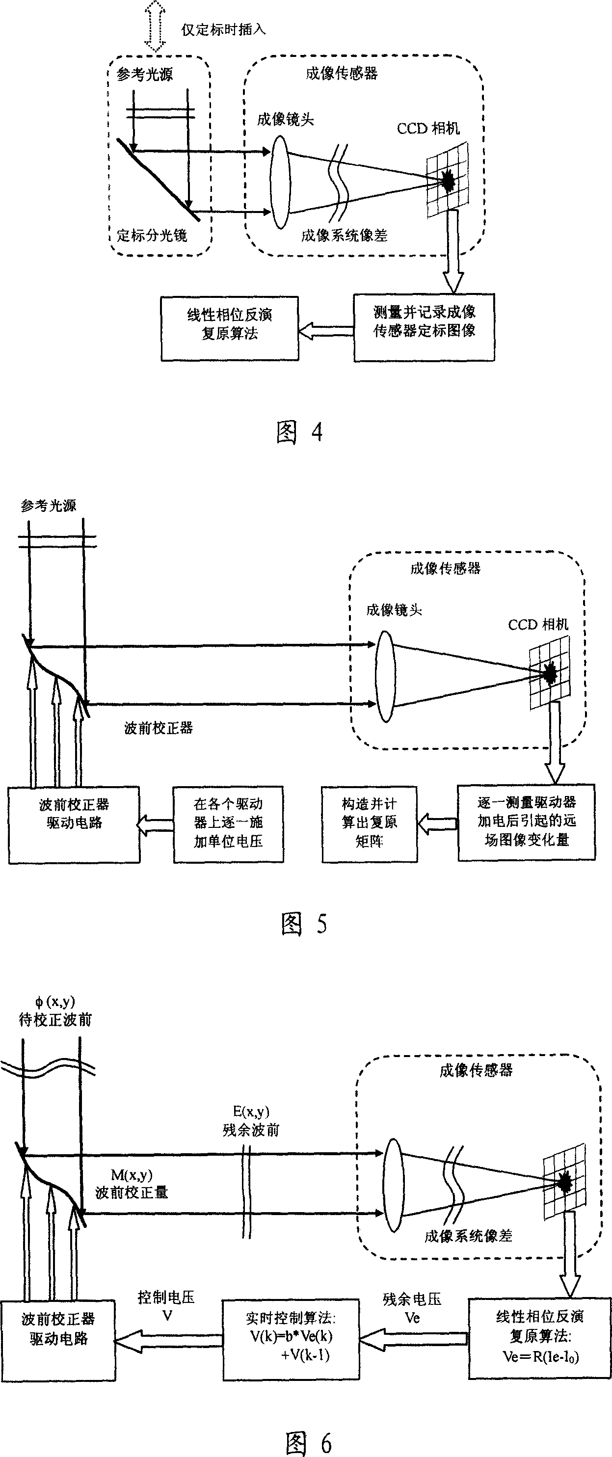
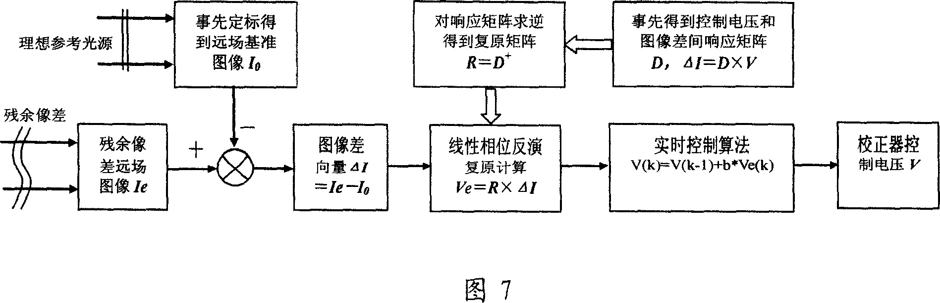
[0052] As shown in Figure 3, an adaptive optics system based on linear phase inversion restoration technology consists of an imaging sensor 1, a linear phase inversion restoration algorithm 2, a real-time control algorithm 3, a wavefront corrector 5 and its driving circuit 4, and a reference light source 6. The calibration beamsplitter 7 is formed, wherein the imaging sensor is composed of a lens 8 and a CCD camera 9. First, the calibration beamsplitter 7 is used to insert the ideal reference light source 6 into the optical path in front of the imaging sensor 1, and the imaging sensor 1 is calibrated and obtained. After the calibration is completed, the reference light source 6 and the calibration beamsplitter 7 are removed. When the adaptive optics system is working, the far-field image of the residual aberration after the wavefront aberration to be corrected is compensated by the wavefront corrector 5 is measured by the imaging sensor 1 in real time, and the obtained image is...


PUM


Abstract

It is an adaptive optics system based on the linear phase inversion recovery technique, comprising the imaging sensor, the linear phase inversion recovery algorithm, the real-time control algorithm, the wave-front correction and drive circuit, and the reference light source. During the system running, the imaging sensor measures the residual aberration far-field image after the compensation of the wave-front correction device, and subtracting with the benchmark image to obtain the image difference vector. In advance, using the reference light source to calibrate the imaging sensor to obtain the benchmark image, and according to the corresponding relations between the wave-front correction device and the imaging sensor, obtaining the recovery matrix between the image difference vector and control voltage. Multiply the image difference vector and the recovery matrix to obtain the corresponding control voltage of the residual wave-front, and use real-time control algorithms, such as proportional integral, to obtain the control voltage of the wave-front correction device, making the wave-front aberration to be corrected. Compared the adaptive optics system based on the linear phase inversion recovery technique and the conventional adaptive optical technology, it has simple structure, high optical energy efficiency, and other advantages.

Description

technical field [0001] The invention belongs to the field of optical technology, and relates to a novel adaptive optical system, in particular to an adaptive optical system based on linear phase inversion restoration technology. Background technique [0002] Adaptive optics is a new optical technology developed in the world over the past 20 years. It uses the combination of electronic technology and optical technology to correct the dynamic optical wavefront error in real time through real-time measurement-control-correction, so that the optical system has the ability to automatically adapt to changes in external conditions and maintain the best working condition. Adaptive optics technology is a powerful means to improve the resolution capability of the imaging system and the beam quality of the laser system. It solves the old problem of dynamic interference that has plagued the optical industry for hundreds of years. etc. have important applications. [0003] As shown in ...

Claims


Application Information

Patent Timeline
IPC IPC(8): G02B26/06G01J9/00
Inventor 李新阳姜文汉凌宁李敏
Owner INST OF OPTICS & ELECTRONICS - CHINESE ACAD OF SCI
Why Eureka
Try Eureka