A compensation method for laser bar thermal lens effect

A technology of thermal lens effect and compensation method, applied in the field of laser rods, can solve the problems of increased laser loss, difficult laser device adoption, and reduced laser energy conversion efficiency, and achieves the effect of simple structure

Inactive Publication Date: 2007-08-15
NINGBO UNIV
View PDF1 Cites 16 Cited by
  • Summary
  • Abstract
  • Description
  • Claims
  • Application Information

AI Technical Summary

Problems solved by technology

But above-mentioned compensating device also has following problem: the compensating method of this compensating device is to make the distance between rod and lens equal to " sum of thermal lens focal length and lens focal length " promptly thermal lens and lens form Keplerian telescope, and this compensating device only when When the focal leng...

Method used


Image

  • A compensation method for laser bar thermal lens effect
  • A compensation method for laser bar thermal lens effect
  • A compensation method for laser bar thermal lens effect

Examples


Embodiment 1

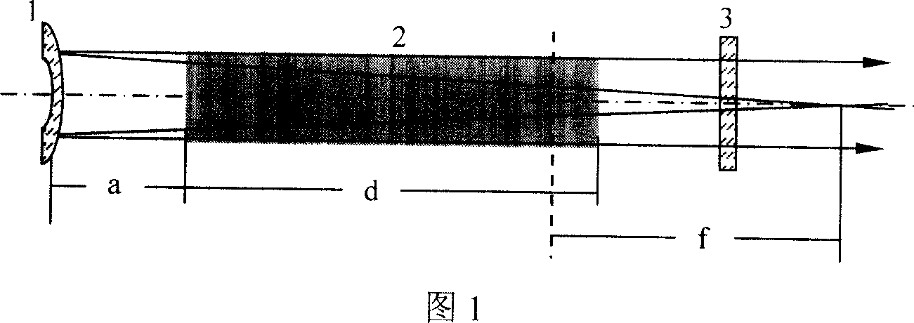
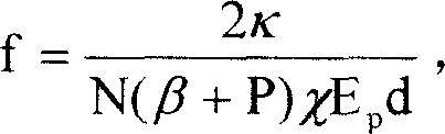
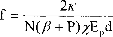
[0009] Embodiment 1: As shown in the figure, 1 is a full-reflection spherical mirror coated with a wavelength of 1053nm, 2 is a φ8×200 N3122 phosphate neodymium glass laser rod, and 3 is a laser output coupling mirror. Glass laser rod volume is 10cm 3 , let the pump energy density E p =20J / cm 3 , the repetition frequency is N=5Hz, the heating efficiency of N3122 glass is χ=0.08, the temperature coefficient of refraction index β=-4.3×10 -6 / °C, stress thermo-optic coefficient P=5.8×10 -6 / °C, thermal conductivity κ=0.0056W / cm°C, rod length d=20cm into the formula f = 2 κ N ( β + P ) χ E p d get glass rod 2 The focal length of the thermal lens is f=47...

Embodiment 2

[0010] Embodiment 2: As shown in the figure, 1 is a spherical mirror coated with a 1064nm total reflection film, 2 is a φ6×100 YAG laser rod, and 3 is a laser output coupling mirror. Set pump energy density E p =15J / cm 3 , the repetition frequency is N=10Hz, the YAG heating efficiency χ=0.05, the temperature coefficient of refraction index β=7.3×10 -6 / °C, stress thermo-optic coefficient P=8×10 -6 / °C, thermal conductivity κ=0.13W / cm°C, rod length d=10cm into the formula f = 2 κ N ( β + P ) χ E p d get the glass rod The focal length of the thermal lens is f=227cm, the radius of curvature R=1.8 f=409cm of the spherical mirror 1 is taken, and f, d valu...


PUM

PropertyMeasurementUnit
Refractive index temperature coefficientaaaaaaaaaa

Abstract

The disclosed thermal-lensing compensation method for laser rod comprises: setting the holophote with a step-motor driving movable mechanism in optical resonator of laser as raised convex mirror toward the laser rod; controlling the step motor by a computer to make the distance from mirror to rod as a = f - R/2 - d/2n. Wherein, R for curvature radius of the mirror, d for rod length, n for refractive index of rod, and f for lens focus. This invention simplifies system structure, affects no energy conversion efficiency, and applies computer to control laser frequency N and pumping energy density Ep for complete automatic compensation.

Description

technical field [0001] The invention relates to a laser rod in a solid-state laser, in particular to a method for compensating the thermal lens effect of the laser rod in the solid-state laser. Background technique [0002] Existing existing solid-state lasers absorb pump light energy during operation, except for a small part that is output in the form of laser, most of the energy is converted into heat and deposited in the laser working material to cause temperature rise, and the pumping is repeated continuously. Under the action of Urawa heat conduction, the temperature gradient in the working substance increases continuously, until the thermal equilibrium is reached when the heating power is equal to the heat taken away by the cooling liquid. The existence of a temperature gradient in the working substance makes the working substance with a completely uniform refractive index become a lens-like medium, and the light beam is focused after passing through the working substa...

Claims


Application Information

Patent Timeline
IPC IPC(8): H01S3/05H01S3/08H01S3/086H01S3/042
Inventor 聂秋华徐铁峰戴世勋杨燕沈祥王训四周亚训董建峰黄国松
Owner NINGBO UNIV
Why Eureka
Try Eureka