Filtering optical read-out micro beam temperature sensor

A temperature sensor and optical readout technology, applied in the field of sensing elements, can solve the problems of long thermal response time, unsatisfactory temperature resolution dynamic response performance, large bending stiffness, etc., to increase and shorten the area-to-volume ratio. Thermal response time, easy reception and handling effects

Inactive Publication Date: 2007-08-22
UNIV OF SCI & TECH OF CHINA
View PDF0 Cites 3 Cited by
  • Summary
  • Abstract
  • Description
  • Claims
  • Application Information

AI Technical Summary

Problems solved by technology

However, the temperature detection sensitivity that can be achieved by this sensing method at present is limited. There are three main reasons for this. First, the method used to detect the deformation of the microbeam is not accurate, which leads to a low temperature resolution of the sensor. ; Second, the size of the currently commonly used dual-material beams is on the order of centimeters, which results in larger bending stiffness and smaller thermal deformation, larger heat capacity, and longer thermal response time, so its temperature resolution (about 0.5°C) and dynamic response performance (response time on the order of seconds) are not ideal; third, when the size of the beam is relatively small (such as the order of microns), it is technically difficult to accurately detect the deformation of the microbeam

Method used


Image

  • Filtering optical read-out micro beam temperature sensor
  • Filtering optical read-out micro beam temperature sensor
  • Filtering optical read-out micro beam temperature sensor

Examples


Embodiment 1

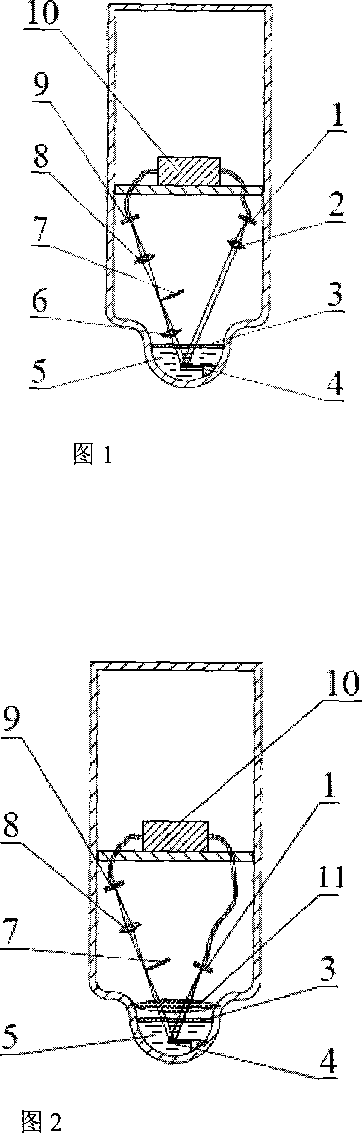
[0034] Referring to Fig. 1, the dual-material microbeam unit 4 is arranged in the temperature sensing head 5, and the point light source 1 is located at the incident side of the microbeam reflector, and is projected on the microbeam reflector;

[0035] On the reflection side of the micro-beam reflector, the linear boundary filter unit 7 is set on the converging spectrum plane of the reflected light from the micro-beam reflector, and the imaging lens 8 is positioned at the rear stage of the linear boundary filter unit 7, and the imaging lens 8 is arranged on the imaging lens 8. The photoelectric receiver 9 on the position is light intensity receiver, light intensity receiver.

[0036] As shown in Fig. 1, the temperature-sensing head 5 is composed of a heat-conducting shell and a closed chamber filled with a heat-conducting liquid. The top cover of the closed chamber is a light-transmitting window 3 that transmits visible light, and the double-material microbeam unit 4 is immerse...

Embodiment 2

[0042] Referring to FIG. 2 , in this embodiment, the same lens 11 is used for the collimation of the illuminating beam of the point light source 1 and the convergence of the reflected beam on the microbeam reflector, that is, the collimating lens and converging lens 11, which simplifies the mechanism.

Embodiment 3

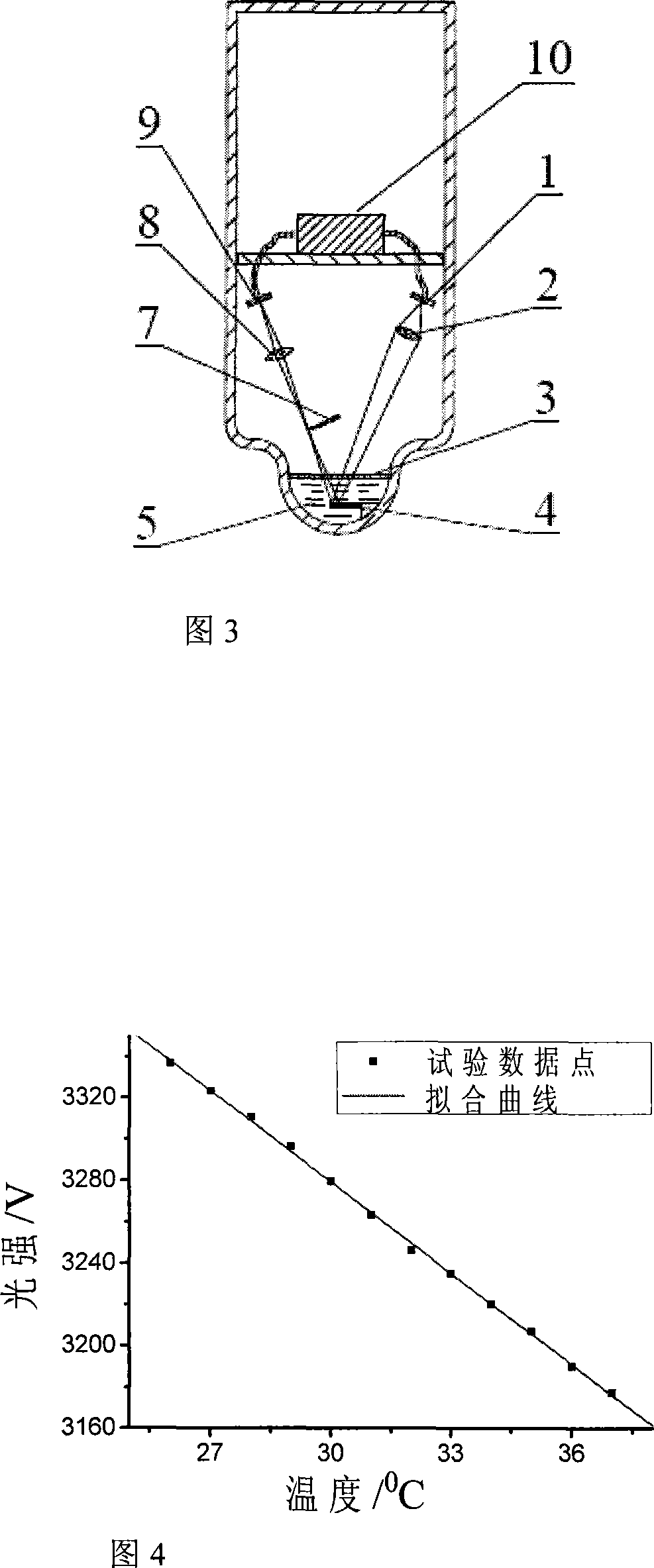
[0044] Referring to Fig. 3, with respect to the above-mentioned embodiment 1 and embodiment 2, in this embodiment, the converging light of the point light source 1 is used as the illumination beam to directly irradiate on the micro-beam reflector, and the reflected beam formed after being reflected by the micro-beam reflector The focal point of the converging light spot is on the plane where the filtering unit 7 is located.

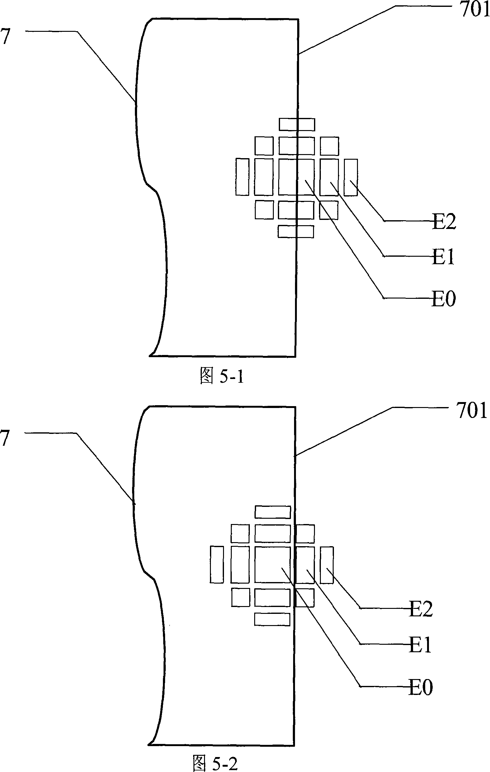
[0045] FIG. 5 shows the relative positional relationship between the diffraction spectrum formed by the light beam reflected by the microbeam on the rear focal plane of the converging lens 6 and the optical filter unit 7 when the structure shown in FIG. 1 is adopted.

[0046] Figure 5-1 shows the relative positional relationship between the optical filter unit 7 and the diffraction spectrum when the microbeam is not heated;

[0047] Figure 5-2 shows the relative positional relationship between the optical filter unit 7 and the diffraction spectrum after t...


PUM

PropertyMeasurementUnit
radiusaaaaaaaaaa
thicknessaaaaaaaaaa
lengthaaaaaaaaaa

Abstract

Filter optical numerating micro-beam temperature sensor, it is characterized in that setting two materials micro-beam unit in temperature response head. Projected light of point-source projects onto micro-beam reflector. Set linear border filter unit on convergent spectrum flat of reflected light from micro-beam reflector and set imaging lens behind linear border filter unit. Set photoelectric receiver on imaging position of imaging lens. The invention uses optical method of linear border filter to detect heat angle distortion of two materials micro-beam free end, which can be applied in temperature change of precise detecting environment.

Description

technical field [0001] The invention relates to a sensor element for detecting ambient temperature, in particular to an optical readout temperature sensor based on a double-material micro-cantilever beam. Background technique [0002] Temperature sensors can be divided into two categories according to different working methods: contact type and non-contact type. Among contact temperature sensors, thermocouples and thermal resistances are commonly used. The most common non-contact temperature sensor is an infrared temperature sensor. [0003] Thermocouples are widely used. The thermocouple is made according to the thermoelectric potential effect. One end of two metal wires of different materials is welded together as the working end, and the unwelded end is the free end. The two wires are called electrodes. When in use, place the working end in the temperature field to be measured, and connect the free end to the meter to measure its potential and keep its temperature cons...

Claims


Application Information

Patent Timeline
Patent Type & Authority Applications(China)
IPC IPC(8): G01K5/48
Inventor 张青川李凯伍小平
Owner UNIV OF SCI & TECH OF CHINA
Why Eureka
Try Eureka