Multi-mode-single mode optical network full optical fiber interconnecting method and interconnector for realizing the same method

A single-mode fiber, multi-mode fiber technology, applied in multi-mode transmission, optical fiber transmission, electrical components and other directions, can solve the problem of low coupling efficiency of single-mode and multi-mode fiber connection, difficult to work as a filter, wavelength tuning, core The coupling between the mode and the cladding mode is complicated, and the effect of easy batch production, guaranteed production accuracy, and wide applicable wavelength range can be achieved.

Inactive Publication Date: 2007-08-22
CHONGQING UNIV
View PDF0 Cites 10 Cited by
  • Summary
  • Abstract
  • Description
  • Claims
  • Application Information

AI Technical Summary

Problems solved by technology

[0006] There are two main problems in the design of multi-mode-single-mode optical fiber network all-fiber interconnectors: one is the low coupling efficiency of single-mode and multi-mode optical fibers; Fiber Bandpass Filter
[0012] When used in the wavelength division multiplexing system of optical communication, this kind of fiber filter has several theoretical disadvantages: first, when used as a band-stop filter, the reflected light is too strong, which is easy to cause interference to the system, especially Affect the work of the laser in the optical communication line; secondly, when used as a bandpass filter, it must be used with a fiber coupler (or become a 2×2 beam splitter), and the light will enter and exit the fiber coupler twice and be split twice , the intensity is attenuated by 4 times (6dB), which greatly increases the requirements for the light intensity in the communication line, and increases the complexity of the system structure; finally, because the principle of FBG is the coupling of the forward propagation core mode and the back propagation core mode , the Bragg wavelength is only related to the refractive index of the fib...

Method used


Image

  • Multi-mode-single mode optical network full optical fiber interconnecting method and interconnector for realizing the same method
  • Multi-mode-single mode optical network full optical fiber interconnecting method and interconnector for realizing the same method
  • Multi-mode-single mode optical network full optical fiber interconnecting method and interconnector for realizing the same method

Examples


Embodiment Construction

[0038] The present invention will be further elaborated below in conjunction with accompanying drawing:

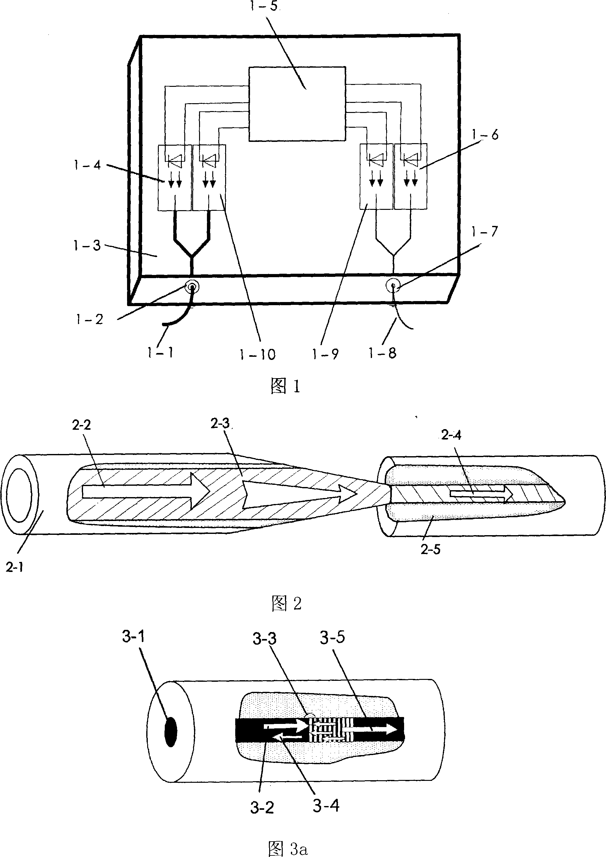
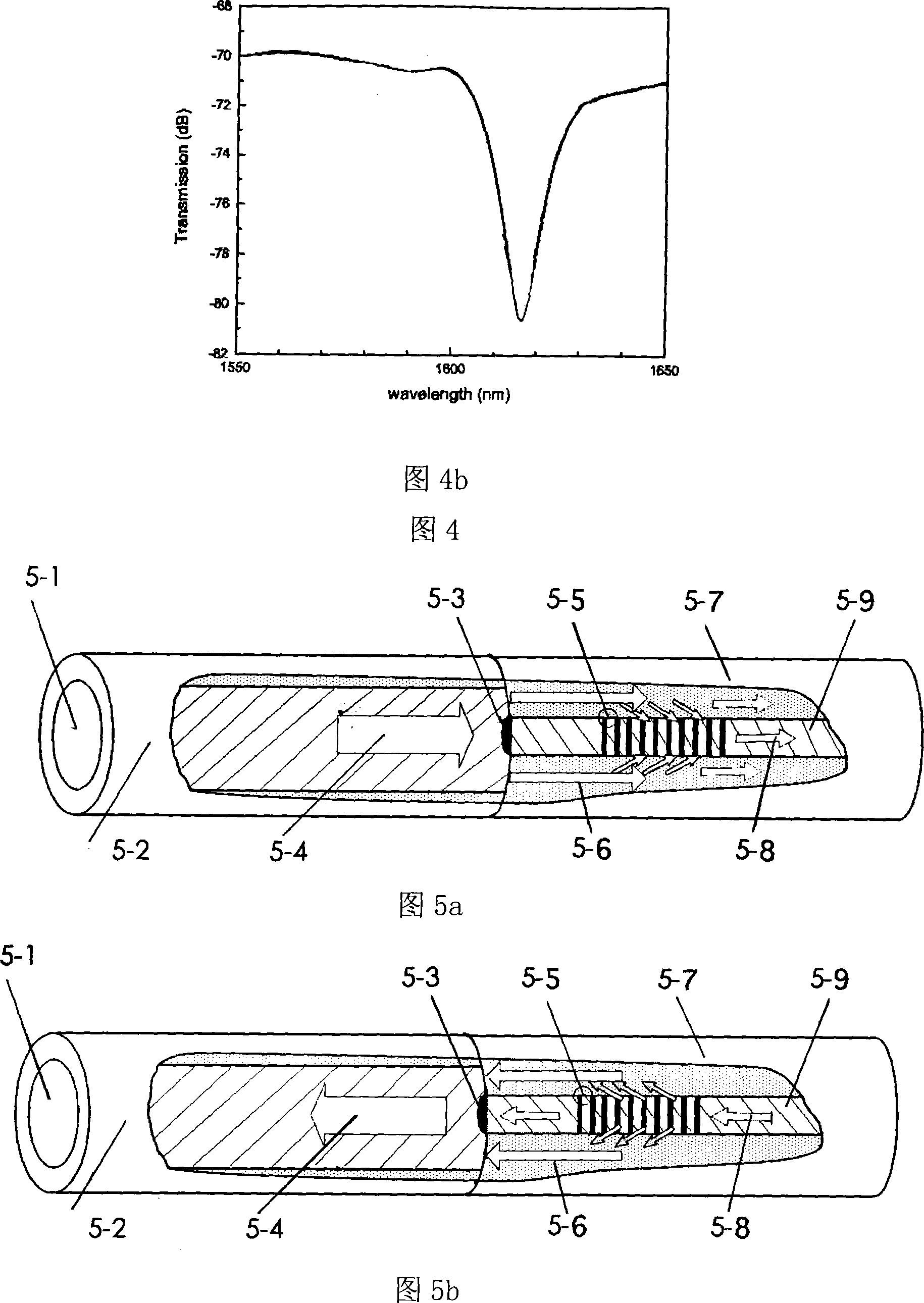
[0039] Referring to Fig. 5 a, the multimode-single-mode optical network all-fiber interconnector includes a multimode fiber 5-2 and a single-mode fiber 5-7, and a long-period fiber grating 5-5 is made on the single-mode fiber 5-7, and the The single-mode fiber core 5-9 end of the front end of the long-period fiber grating 5-5 is made with a metal titanium tungsten coating as the core mode absorber 5-3, and the diameter of the core mode absorber 5-3 is 9 microns, and The single-mode optical fiber cores 5-9 have the same diameter, and the core-mode absorber can be manufactured by photolithography and coating technology in micro-electromechanical systems (MEMS) and micro-nano manufacturing technology. The specific steps are as follows:

[0040] 1) Making long-period fiber gratings;

[0041] 2) Treat its rear end surface into a mirror surface;

[0042] 3) Treat the end face ...


PUM


Abstract

A method for interconnecting all-optical fiber of multimode-singlemode optical network includes connecting normal multimode optical fiber with LPFG, preparing a core mould absorber with the same diameter as fiber core on LPFG long end surface fiber core at connector position for using it to block light transmission in multimode optical fiber to single-mode optical fiber core but not influencing light transmission in multimode optical fiber to single-mode optical fiber covering to from a band pass filter.

Description

technical field [0001] The invention belongs to the field of optical fiber passive devices and the technical field of micro-electromechanical systems (MEMS), and in particular relates to a multi-mode-single-mode optical network all-fiber interconnector. Background technique [0002] The local area network (LAN) market has developed rapidly in the past ten years, and the demand for short-distance computer high-speed interconnection has made the data rate of the LAN grow exponentially: from 10Mb / s to 1Gb / s to 10Gb / s, the laboratory of multimode optical fiber LAN in 2006 The data transmission rate has reached 1000Gb / s; it has become an inevitable trend that the optical fiber LAN replaces the traditional unshielded twisted pair LAN. However, due to the high cost, it is difficult to directly popularize and apply the wide area network and backbone network technology based on dense wavelength division multiplexing (DWDM) technology and single-mode optical fiber network in the local...

Claims


Application Information

Patent Timeline
IPC IPC(8): H04B10/12H04B10/207H04B10/2581
Inventor 朱永梅浩陈伟民符欲梅
Owner CHONGQING UNIV
Why Eureka
Try Eureka