Method for continuouslly monitoring gas well-boring state under well

A gas drilling and state technology, used in wellbore/well components, measurement, earthwork drilling, etc., can solve the problems of slow instrument response, high production cost, large volume, etc., and achieve the effect of ensuring safety and efficiency

A gas drilling and state technology, used in wellbore/well components, measurement, earthwork drilling, etc., can solve the problems of slow instrument response, high production cost, large volume, etc., and achieve the effect of ensuring safety and efficiency

CN101029564AInactive Publication Date: 2007-09-05SOUTHWEST PETROLEUM UNIV

Image

  • Method for continuouslly monitoring gas well-boring state under well
  • Method for continuouslly monitoring gas well-boring state under well
  • Method for continuouslly monitoring gas well-boring state under well

Examples


Embodiment approach

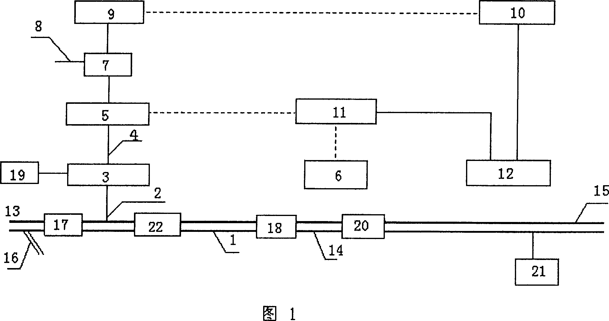
[0014] (1) The normal dust drilling state of gas drilling. In the normal dust drilling state, no oil, gas and water are produced in the formation, and the downhole rock breaking is normal and the rock cleaning is smooth. At this time, according to the injected gas volume and drilling speed, combined with the monitoring values ​​of the upstream pressure sensor 13, the midstream pressure sensor 14 and the momentum sensor 22, the return gas flow rate and mixing density can be calculated. The removal state and quantity of granular rock debris are monitored by the broadband sound sensor 18, and the dust state, quantity and color are observed by the all-weather observation camera system 6 at the outlet. If the addition of the dust-reducing water 21 is stopped, the effect will be better. Open the cuttings sampler 16 intermittently to obtain geological sand samples.

[0015] (2) Well plugged drilling state of gas drilling. If there is obvious blockage in the annular space during dri...


PUM


Abstract

A continuous monitor method for oil well includes: sampling the gas at the spigot line; after de-dust and de-water procedure, the gas flow through a flow meter and monitor system to the analysis instrument; the analysis data is collected and sent to a PC module, so to realize auto-monitor, analysis and comparison.

Description

technical field [0001] The invention relates to a method for monitoring, analyzing and judging the downhole state of gas drilling used in the oil and gas exploitation industry to ensure the safety and high efficiency of drilling. A continuous monitoring method for the downhole state of gas drilling, which is also applicable to hydrology, geothermal, mineral resources Gas drilling in other fields. Background technique [0002] At present, gas drilling refers to a drilling method in which gases such as air, natural gas, nitrogen, and combustion tail gas are used as circulating media. Gas drilling can greatly increase drilling speed, reduce costs and shorten drilling cycle. Gas drilling can also effectively overcome downhole complex situations such as lost circulation and shale collapse. The use of gas drilling in oil and gas reservoirs can well protect the oil and gas layers, increase the discovery rate in exploration wells, and increase the productivity of oil and gas wells...

Claims


Application Information

Patent Timeline
05 Sep 2007
Publication
CN101029564A
IPC
E21B47/00; E21B49/00; E21B47/002
Inventors
孟英峰; 李永杰