Unlock instant, AI-driven research and patent intelligence for your innovation.

Induction motor rotor with the reduced crosscurrent and leakage magnetic flux function

An induction motor and leakage flux technology, applied in the direction of magnetic circuit rotating parts, manufacturing stator/rotor body, magnetic circuit shape/style/structure, etc., can solve the problem of cross current and rotor leakage flux, reduce cross current current and leakage flux, low motor peak torque, etc., to achieve good application prospects, suppress vibration, and improve the effect of output torque

Inactive Publication Date: 2007-09-12
HARBIN INST OF TECH
View PDF0 Cites 7 Cited by
  • Summary
  • Abstract
  • Description
  • Claims
  • Application Information

AI Technical Summary

Problems solved by technology

[0006] In order to solve the problem that the existing induction motor rotor produces cross-current current and rotor leakage flux, which makes the motor efficiency decrease and the peak torque of the motor is low, an induction motor rotor with the function of reducing cross-current current and leakage flux is proposed.

Method used


Image

  • Induction motor rotor with the reduced crosscurrent and leakage magnetic flux function
  • Induction motor rotor with the reduced crosscurrent and leakage magnetic flux function
  • Induction motor rotor with the reduced crosscurrent and leakage magnetic flux function

Examples


specific Embodiment approach 1

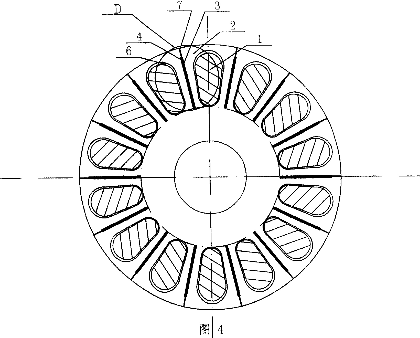
[0010] Specific Embodiment 1: This embodiment is described with reference to FIGS. 1 to 10. This embodiment is composed of a winding 1, a rotor core 2, and a thin metal plate 4 with an insulating layer on the surface; between any two winding slots 6 of the rotor core 2 Along the axial direction of the rotor core 2, there is a rectangular magnetic isolation narrow slot 3, the notch center line of the magnetic isolation narrow slot 3 is on the diameter of the rotor core 2, the long side of the notch of the magnetic isolation narrow slot 3 and the magnetic isolation narrow slot The centerlines of the notches of 3 are parallel, and the thin metal plate 4 with an insulating layer on the surface is embedded in the magnetic isolation narrow groove 3.

[0011] The thin metal plate 4 with an insulating layer on the surface has an insulating effect and can block the cross-current current between any two adjacent bars of the winding 1, so it can reduce the loss caused by the rotor leakage...

specific Embodiment approach 2

[0012] Specific embodiment 2: This embodiment is described in conjunction with Fig. 1 to Fig. 10. The difference between this embodiment and specific embodiment 1 is that the magnetic isolation narrow slot 3 and the slot bottom of the winding slot 6 are on the same circumference, and the magnetic isolation narrow slot 3 The radial length is smaller than the maximum radial length of the winding slot 6, effectively ensuring the magnetic circuit width of the yoke of the rotor. Other compositions and connection methods are the same as those in Embodiment 1.

specific Embodiment approach 3

[0013] Embodiment 3: The difference between this embodiment and Embodiment 2 is that the width of the magnetic isolation narrow slot 3 is between 0.2 mm and 1.5 mm, effectively ensuring the radial magnetic path width of the rotor teeth. Other compositions and connection methods are the same as those in the second embodiment.


PUM

PropertyMeasurementUnit
Widthaaaaaaaaaa

Abstract

The invention relates to an induction machine rotor which has the function of reducing the crossflow electric current and leakage flux, it relates to a machine rotor, for solving the problem of the existing induction machine rotor produce much crossflow electric current and rotor leakage flux, made the electrical efficiency drop and the electrical machinery peak value torque low. Between wilfully two windings troughs (6) of its rotor iron core (2) along the rotor iron core axial direction have the rectangle separate magnetism narrow groove (3), the notch center line of magnetism narrow groove (3) set on the rotor iron core (2) diameter, causes the question. separates the notch long side of separate magnetism narrow groove (3) in parallel with the notch center line of magnetism narrow groove (3), the metal thin plate (4) embedded in the separate magnetism narrow groove(3). It reduces the loss which the rotor leakage flux and the crossflowelectric current causes, enhances the electrical machinery output torque; at the same time, also can suppress the vibration, noise and unusual torque production which the electrical machinery produces, have good application prospect in the electric power domain.

Description

technical field [0001] The invention relates to a motor rotor. Background technique [0002] The induction motor uses the principle of electromagnetic induction to generate a rotating magnetic field through the three-phase current of the stator, and interacts with the induced current in the rotor winding to generate electromagnetic torque for energy conversion. Under normal operating conditions, the rotor speed of an induction motor is always slightly lower or slightly higher than the speed of the rotating field (synchronous speed n s ), so the induction motor is also called "asynchronous motor". The rotational speed of the rotating magnetic field n s The difference from the rotor speed n is called the slip, and the slip Δn is related to the synchronous speed n s The ratio of is called the slip rate, denoted by s, that is [0003] s = n s - n ...

Claims


Application Information

Patent Timeline
IPC IPC(8): H02K1/26H02K15/02
Inventor 寇宝泉李立毅白相林
Owner HARBIN INST OF TECH