Whirl entraining type cooking fume exhauster

A range hood and swirl tank technology, which is applied in the direction of oil fume removal, heating methods, household heating, etc., can solve the problems of low efficiency of oil fume suction and exhaust, easy to block the line of sight, poor air flow, etc., and achieve the improvement of oil fume extraction rate, Mutual interference is eliminated and the function does not degrade

Inactive Publication Date: 2007-09-26
UNIV OF SCI & TECH OF CHINA
View PDF3 Cites 11 Cited by
  • Summary
  • Abstract
  • Description
  • Claims
  • Application Information

AI Technical Summary

Problems solved by technology

However, the existing electric range hoods on the market almost all set the fan in the pipeline at the junction of the smoke collection hood and the smoke exhaust pipe, and use the rotation of the fan impeller to generate negative pressure to suck the oil fume. The blades of the fan directly contact the fume gas. contact, causing the blades of the fan to stick to oil, destroying the balance of the blades, making it difficult to clean, reducing the performance of the fan, increasing the noise, and shortening the life of the range hood; and because the exhaust pipe is blocked by the fan, the airflow is not smooth, The efficiency of sucking and exhausting oil fume is very low; manufacturers often increase the input power of the fan to make up for it, which not only increases the energy consumption, but also increases the noise of the fan, making some electric range hoods unable to meet the "GB/T17713-1999 Oil Suction Smoke machine" national standard and the requirements of "Residential Design Code GB50096-1999"
If the original structural state does not change, the defects of the existing electric range hoods, such as low efficiency of sucking and exhausting oil fume, high energy consumption, high noise, high pollution, difficult cleaning and short service life, cannot be changed.
[0003] The "swirl type range hood" proposed in Chinese Patent No. 01201987.9, although the configured fan is removed from the smoke exhaust pipe, and the swirling airflow is u

Method used


Image

  • Whirl entraining type cooking fume exhauster
  • Whirl entraining type cooking fume exhauster
  • Whirl entraining type cooking fume exhauster

Examples


Embodiment 1

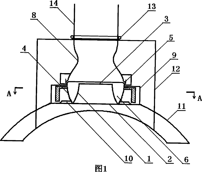
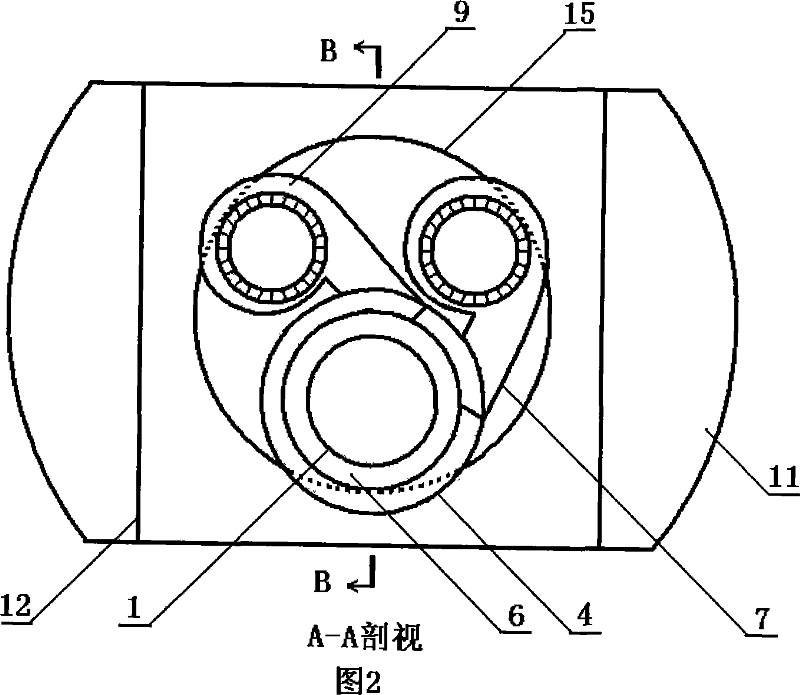
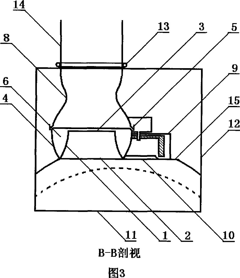
[0027] This embodiment is an implementation manner of a swirling flow range hood. Fig. 1 is a schematic diagram of its longitudinal sectional structure, Fig. 2 is a schematic diagram of the A-A sectional structure of Fig. 1 , and Fig. 3 is a schematic diagram of the B-B sectional structure of Fig. 2 .

[0028] As shown in Fig. 1, Fig. 2 and Fig. 3: the swirling oil fume suction device adopted in this embodiment is a sleeve-shaped device, that is, the trumpet-shaped inner cylinder 1 with the central axis extends into the outer cylinder 4, An annular swirl groove 6 with a "v" shape in cross section and a sealed groove bottom is formed. The generatrix of the inner tube 1 of the horn is hyperbolic, the diameter of the lower opening is 1.25 times the diameter of the upper opening 3, and the height is 1.25 times that of the upper opening 3. 0.5 times the diameter of the mouth 3, the generatrix of the outer cylinder 4 is parabolic, the diameter of the upper opening is 1.2 times the d...

Embodiment 2

[0034] This embodiment is another implementation of the swirling flow range hood. Fig. 4 is a schematic view of its longitudinal section structure, Fig. 5 is a schematic view of a C-C sectional structure of Fig. 4 , and Fig. 6 is a schematic view of a D-D sectional structure of Fig. 5 .

[0035] As shown in Fig. 4, Fig. 5 and Fig. 6: the structure and connection mode of the swirling oil fume suction device, the annular oil cut-off groove 5, and the double-sided sealed rolling door 13 adopted in this embodiment are the same as those in embodiment 1, and the difference The location is: the spherical smoke collecting hood 11 is installed in an inclined and low position, so that the smoke collecting hood 11 has a low smoking port 16 that is closer to the stove, and the corresponding smoking port 2 that is farther from the stove is a high smoking port. Under the air inlet 10 of the blower fan, a draft guide tube 17 is stretched out and connected to the low-position smoke opening 16...


PUM


Abstract

A swirl drawing oil exhaust ventilator features in the stacked arrangement of two wind machine and ring swirl slot, two wind blower pipe tangentially cutting the ring swirl slot with an included angle of 60-180, outside barrel connected to the radius change connecting pipe, slot at their juncture and outside slanted slot, a ring oil stop slot, radius change minimum diameter being 0.9 to 1.3 times of the up opening diameter of the connecting pipe, length being 1 to 2 times of the minimum diameter, radius connecting pipe installed with dual sealing rolling door at the joint position of the smoke exhaust chimney. It adopts reasonable assembly method, linear structure and ball smoke hood, free from big power wind blower to achieve better bump effect, getting rid of may setbacks of existing electric smoke extraction machine with high efficiency, energy saving, environment protective and easy cleaning.

Description

Technical field: [0001] The invention belongs to the technical field of pneumatic dust removal devices, and in particular relates to an electric range hood for removing oil fume gas, in particular to a swirl roll-type range hood. Background technique: [0002] Electric range hoods have been in the ranks of household appliances for half a century, and they are indispensable fume purifiers in the kitchen environment. However, the existing electric range hoods on the market almost all set the fan in the pipeline at the junction of the smoke collection hood and the smoke exhaust pipe, and use the rotation of the fan impeller to generate negative pressure to suck the oil fume. The blades of the fan directly contact the fume gas. contact, causing the blades of the fan to stick to oil, destroying the balance of the blades, making it difficult to clean, reducing the performance of the fan, increasing the noise, and shortening the life of the range hood; and because the exhaust pipe ...

Claims


Application Information

Patent Timeline
IPC IPC(8): F24C15/20
Inventor 司廷丁德厚尹协振
Owner UNIV OF SCI & TECH OF CHINA
Why Eureka
Try Eureka