Electric power supply control apparatus

A technology of power control device and animal electricity, which is applied in the direction of circuit device, battery circuit device, measuring device, etc., and can solve the problems of shortened battery system life and poor maintainability

Inactive Publication Date: 2007-09-26
HITACHI LTD
View PDF1 Cites 39 Cited by
  • Summary
  • Abstract
  • Description
  • Claims
  • Application Information

AI Technical Summary

Problems solved by technology

Therefore, when only a certain battery is degraded, in the prior art that completely separates the degraded battery from the parallel structure, the time period when the required current cannot be obtained is shortened, so it can be said that the life of the battery system is shortened.
[0007] In addition, when the deteriorated battery separated from the system is replaced with a new battery, it can be said that the maintainability is poor because the difference in battery deterioration is less than that of the other batteries and it does not need to be replaced, because it needs to be replaced at the next timing.

Method used


Image

  • Electric power supply control apparatus
  • Electric power supply control apparatus
  • Electric power supply control apparatus

Examples


Embodiment 1

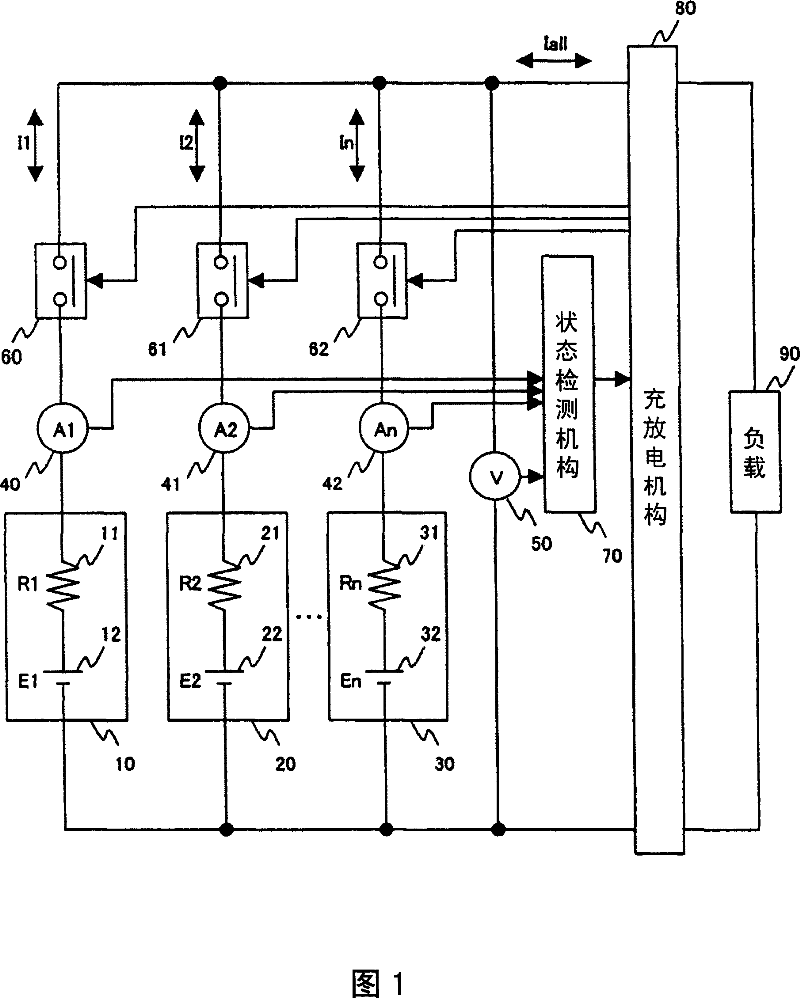
[0023] FIG. 1 shows the structure of the power control device of this embodiment. Before explaining FIG. 1 , an operation example of a power supply control device of a type that detects a deteriorated battery and separates from a parallel structure in the prior art shown in FIG. 7 , which is the premise of the present invention, will be described.

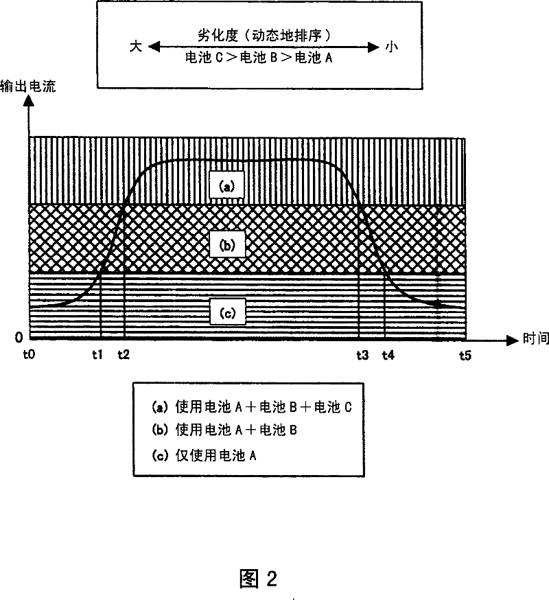
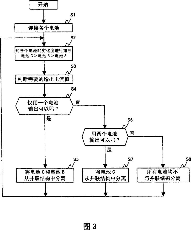
[0024] In the conventional power control device of FIG. 7 , a plurality of secondary batteries (abbreviated as batteries in the following description) are connected in parallel, and a switch capable of separating the batteries is provided to each column. Here, a configuration in which three batteries of battery A, battery B, and battery C are connected in parallel will be described. In such a power supply control device, during time t0 to t1 ((a) in the figure), three batteries, battery A, battery B, and battery C, are used to obtain a required output current. At the next time t1, battery C is separated from the parallel configura...

Embodiment 2

[0043] FIG. 5 shows the configuration of the voltage control device of this embodiment. It is basically the same as in FIG. 1 of the first embodiment, except that a state signal is output from the load 90 to the charging and discharging mechanism 80 . The status signal is information about the current value required by the load 90 in the future or the speed of the vehicle driven by the load 90 at present. The charging and discharging mechanism 80 switches the livestock electric mechanism 10 , 20 , 30 to be used based on the state signal and the degree of deterioration of the livestock electric mechanism 10 , 20 , 30 . Thus, because the current value required by the load 90 is known in advance, the charging and discharging mechanism 80 can switch the animal electric mechanism 10, 20, 30 in advance, and can obtain the output current smoothly.

Embodiment 3

[0045] FIG. 6 shows the structure of the power control device of this embodiment. Basically, it is the same as in FIG. 1 of the first embodiment, except that resistors 100 , 101 , 102 and switches 110 , 111 , 112 are connected in parallel to switch mechanisms 60 , 61 , 62 . The resistors 100, 101, 102 prevent a large inrush current from flowing when the switch mechanisms 60, 61, 62 are turned on. For example, when the livestock electric mechanism 10 is used, the switch mechanism 110 is turned on before the switching mechanism 60 is turned on, and then the switch mechanism 60 is turned on, thereby preventing a large inrush current from flowing into the livestock electric mechanism 10 .


PUM


Abstract

An electric power supply control apparatus according to the present invention is connected in parallel to plural electric storage means and comprises: plural current measurement means which respectively measure the currents of the plural storage means connected in parallel; plural voltage measurement means which respectively measure the voltages of the plural storage means connected in parallel; plural switching means which respectively disconnect and connect the plural electric storage means from and to the parallel connection; state detection means which receives the outputs of the current measurement means and the outputs of the voltage measurement means and outputs the respective states of the plural electric storage means; and charging and discharging means which receives the outputs of the state detection means and charges and discharges the plural electric storage means. The charging and discharging means judges the deterioration states of the plural electric power storage means from the outputs of the state detection means and, based on the judged respective deterioration states of the plural electric storage means, controls switching of the plural switching means.

Description

technical field [0001] The present invention relates to a power supply control device for controlling charging and generating power of lead batteries, nickel hydrogen batteries, lithium ion batteries and the like using a livestock electric mechanism. Background technique [0002] Generally, secondary batteries such as lead batteries, nickel metal hydride batteries, or lithium ion batteries are mounted in electric vehicles or hybrid vehicles. Compared with lead batteries, nickel-hydrogen batteries or lithium-ion batteries have higher energy density, can form multiple series / multiple parallel connections, and are mainly used for vehicle driving. Especially in a large-scale battery system that requires a large current, a structure in which multiple batteries are connected in parallel is adopted. [0003] The state of charge (SOC: state of charge) or the state of deterioration (SOH: state of health) of the secondary battery changes by repeated charging and discharging. Generall...

Claims


Application Information

Patent Timeline
Patent Type & Authority Applications(China)
IPC IPC(8): H02J7/00H01M10/44
CPCH02J7/0075H01M10/482Y02E60/12Y02T10/7055H02J7/0021H01M10/345H01M10/052G01R31/3658Y02T10/7011H01M10/46H01M10/30G01R31/3679G01R31/3624H02J2007/0067H02J7/0031H01M10/441G01R31/3842G01R31/392G01R31/396H02J7/0069Y02T10/70Y02E60/10H02J7/0016H02J7/0013H02J7/0019H02J7/005H02J7/00712
Inventor 城学江守昭彦河原洋平铃木优人
Owner HITACHI LTD
Why Eureka
Try Eureka