Coupled methane tank

A biogas tank and conjoined technology, which is applied in the fields of biogas generation devices and sewage treatment, can solve the problems of inability to meet farmers' biogas needs, difficulty in deep excavation and high cost, and achieve the effects of being conducive to heat preservation, ensuring efficiency and efficient fermentation.

Inactive Publication Date: 2010-07-21
朱涛 +1
View PDF6 Cites 1 Cited by
  • Summary
  • Abstract
  • Description
  • Claims
  • Application Information

AI Technical Summary

Problems solved by technology

There are several deficiencies in the following aspects: on the one hand, it cannot meet the needs of farmers for biogas, and the amount of raw materials used by farmers for domestic fermentation has greatly exceeded the capacity of traditional biogas digesters. If it is some farms that raise livestock, then it is necessary to build more A biogas digester or even a dozen can meet the demand
However, due to the limitation of geological conditions, it is difficult to dig deep. The deeper the construction, the higher the cost, which limits the expansion of the biogas tank capacity.

Method used


Image

  • Coupled methane tank
  • Coupled methane tank
  • Coupled methane tank

Examples


Embodiment 1

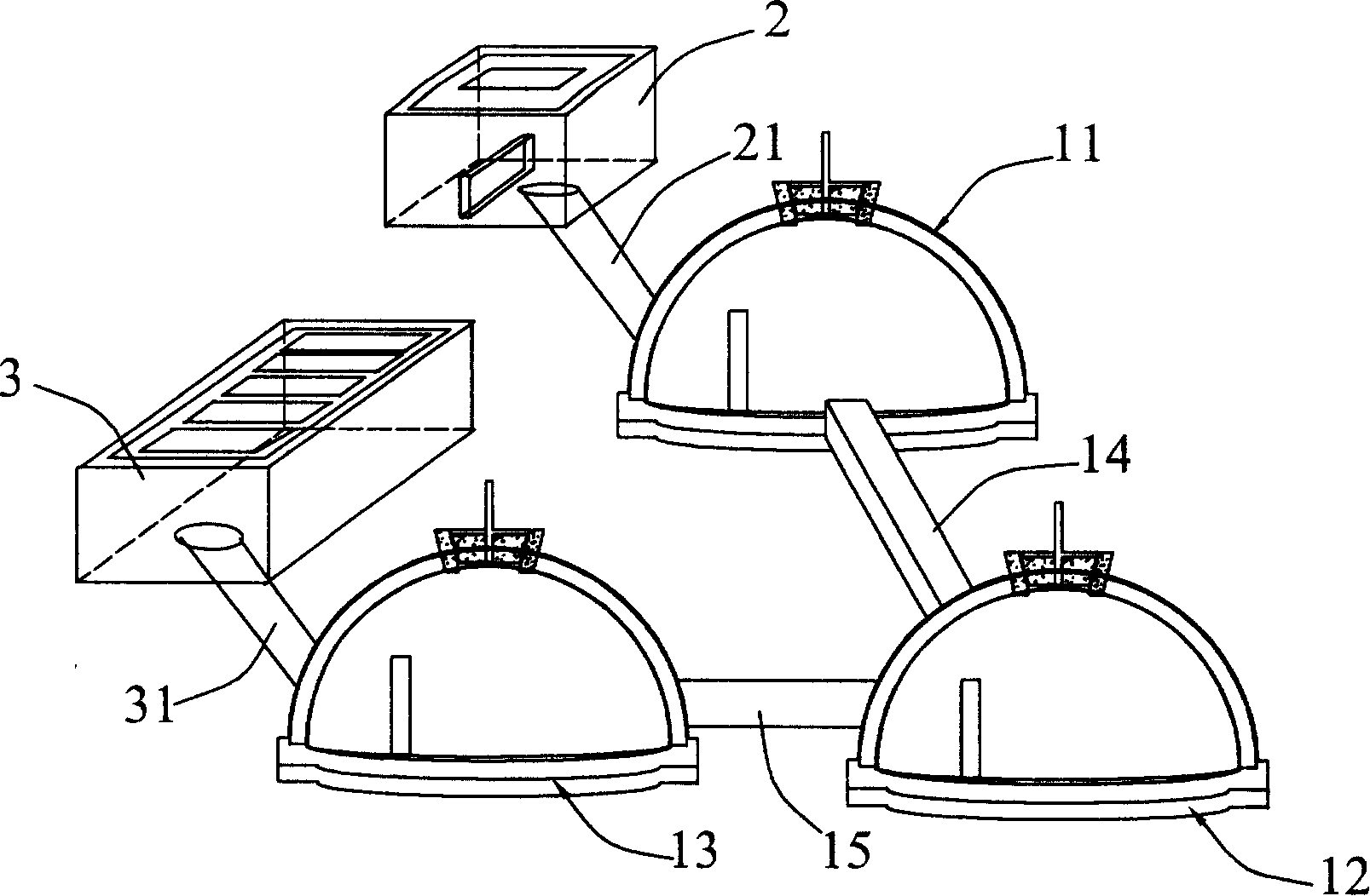
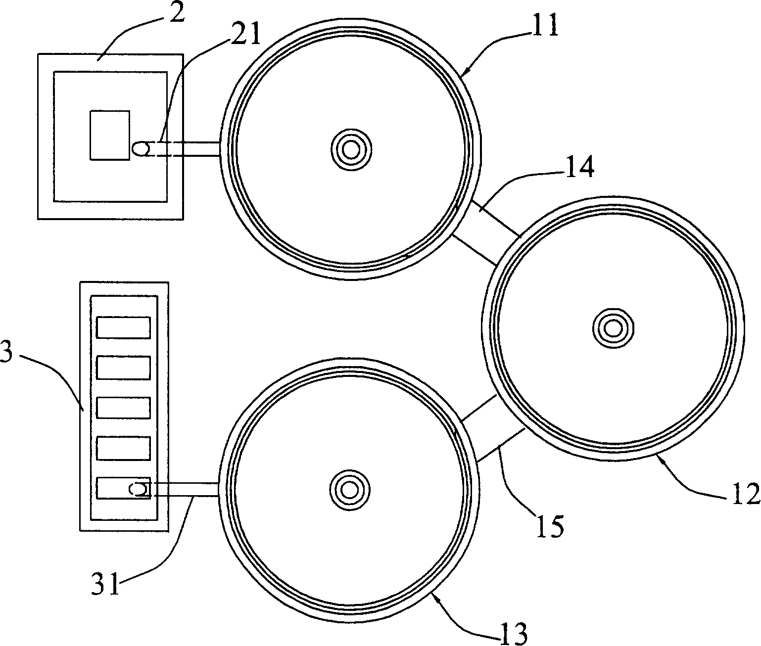
[0040] This embodiment is a biogas digester with a three-tank tandem structure. The structure mainly includes a feed tank 2, a first fermentation tank 11, a second fermentation tank 12, a third fermentation tank 13, and a feed tank 2 connected to the feed tank 2 through a feed pipe 21. The third fermentation tank 13 is connected to the discharge tank 3 through a discharge pipe 31, and the second fermentation tank 12 is communicated with the first fermentation tank 11 and the third fermentation tank 13 through communication pipes 14 and 15 respectively. The arrangement of the various structures of the biogas digester is as follows figure 2 As shown, the three fermentation tanks are arranged in a triangle to save land space.

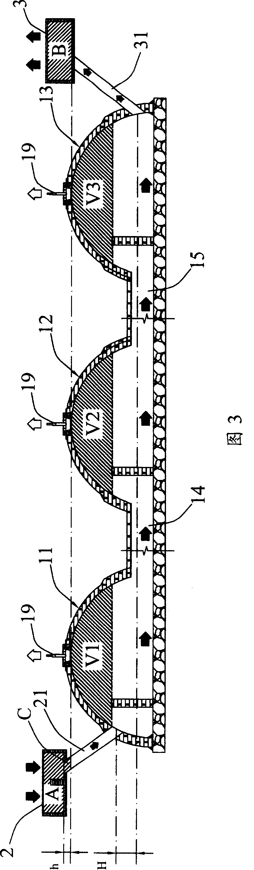
[0041] The detailed internal structure and dimensions of the biogas digester are shown in Figure 3. For the convenience of illustration, Figure 3 arranges three fermentation tanks in a straight line. The feed tank 2 and the discharge tank 3 are connected to e...

Embodiment 2

[0047] Such as Image 6 The illustrated four-pot biogas tank in series is composed of a feed tank 2, a first fermentation tank 11, a second fermentation tank 12, a third fermentation tank 13, a fourth fermentation tank 4, and a discharge tank 3 in series. The internal structure and working principle of the fermentation tank are basically the same as in Example 1. Compared with Example 1, this embodiment has a larger capacity, and the fermentation liquid is reacted for a longer time in the biogas tank, and the degree of degradation is more sufficient.

Embodiment 3

[0049] This embodiment is a further improvement on the basis of embodiment 2, and also has a special gas storage device. The gas storage device is composed of two gas storage tanks 51, 52 connected at the bottom with the same structure as the biogas tank, and two hydraulic tanks 53 respectively connected to the gas storage tank 52. The tops of the gas storage tanks 51, 52 are connected to the gas storage ports on the tops of the fermentation tanks through pipes 55, 56. During use, a certain amount of water is filled in the hydraulic tank 53. When a biogas chamber is formed on the top of the fermentation tank, the air pressure generated by the gas chamber transports the biogas to the gas storage tanks 51, 52 through the pipes 55 and 56 to form the same Air chamber. The air chambers in the air storage tanks 51 and 52 form a certain pressure to raise the liquid level of the hydraulic tank 53 to form a hydraulic seal. The first fermentation tank 11, the second fermentation tank 1...


PUM


Abstract

The present invention relates to methane generating apparatus and sewage treating technology, and is especially one kind of coupled methane tank capable of treating great amount of domestic garbage to produce methane through complete degradation. Structurally, the coupled methane tank includes one feeding tank with gas outlet, two or more fermenting tanks, one discharging tank and connecting pipeline to form liquid flow passage. Through stage-by-stage reaction in the fermenting tanks, the present invention produces methane.

Description

technical field [0001] The invention relates to the field of biogas generating device and sewage treatment, more specifically to a conjoined biogas digester with super large capacity, capable of providing a large amount of biogas and simultaneously treating domestic sewage, feces and the like. technical background [0002] Biogas is a combustible gas. In the rural areas of our country, it is a combustible gas produced by using organic matter such as human and animal manure under anaerobic conditions through the energy metabolism and respiration of microorganisms in the biogas tank. There are 5 people in an ordinary farm family, and 4 pigs and 1 cow are kept normally. The human and livestock feces discharged annually can produce 810-950m3 biogas per year according to theoretical calculations. After deducting the loss of manure and the pressure loss of biogas fermentation, the actual usable biogas is 500-550m3 . In the prior art, the utilization of biogas is mainly realized t...

Claims


Application Information

Patent Timeline
Patent Type & Authority Patents(China)
IPC IPC(8): C12M1/107
CPCY02E50/343Y02E50/30
Inventor 朱涛胡康利
Owner 朱涛
Why Eureka
Try Eureka