Metal-isolator-metal transformer and its manufacturing method

A manufacturing method and insulator technology, which is applied in the direction of inductance/transformer/magnet manufacturing, fixed transformer or mutual inductance, transformer/inductor coil/winding/connection, etc., which can solve the problems of increased cost, low transformer coefficient, and large radio frequency circuit area and other issues, to achieve the effect of improving component performance, saving process costs, and improving coupling coefficient

Active Publication Date: 2007-10-03
UNITED MICROELECTRONICS CORP
View PDF0 Cites 11 Cited by
  • Summary
  • Abstract
  • Description
  • Claims
  • Application Information

AI Technical Summary

Problems solved by technology

Among them, the coplanar transformer is fabricated on the same plane, so its occupied area is too large, and this will cause the designed RF circuit area to be too large, resulting in an increase in cost
In addition, the space between the two coils of the non-coplanar transformer is large, which will cause the problem that t

Method used


Image

  • Metal-isolator-metal transformer and its manufacturing method
  • Metal-isolator-metal transformer and its manufacturing method
  • Metal-isolator-metal transformer and its manufacturing method

Examples


Embodiment Construction

[0038] The existing transformer has problems such as large area and large space between coils, which affect the process cost and device performance. Therefore, the present invention proposes a metal-insulator-metal transformer and a manufacturing method thereof to solve the above problems.

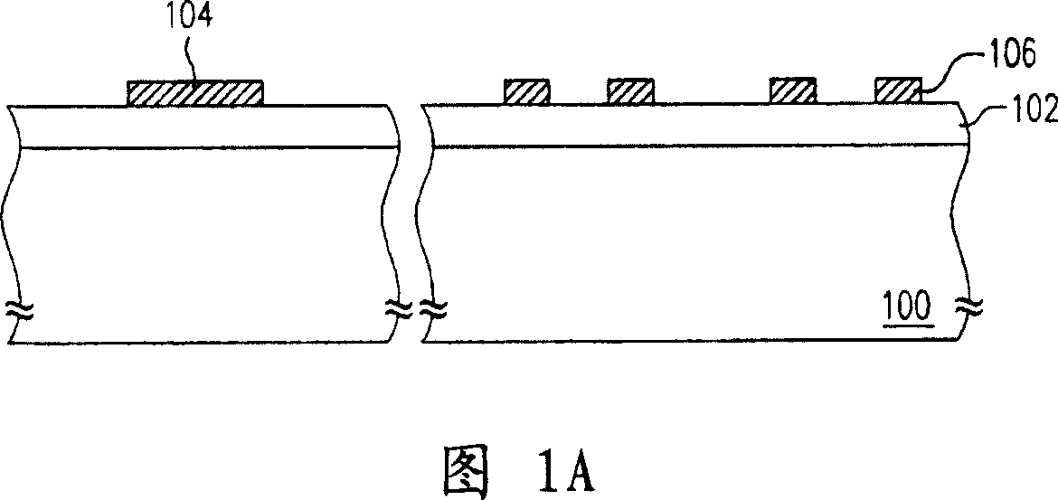
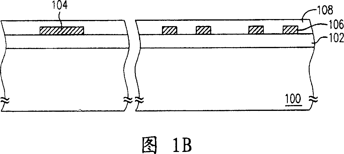
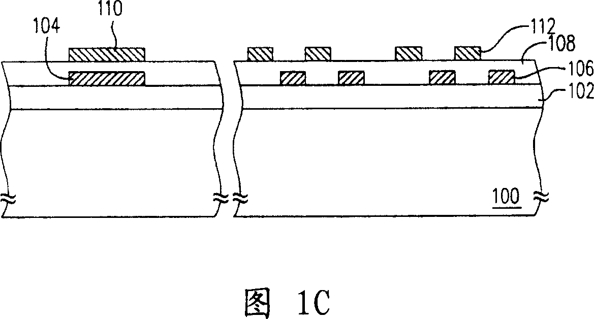
[0039] 1A to 1C are schematic cross-sectional views of a manufacturing method of a metal-insulator-metal transformer according to an embodiment of the present invention.

[0040] First, please refer to FIG. 1A , a substrate 100 is provided, and at least a dielectric layer 102 is formed on the substrate 100 . The material of the dielectric layer 102 is, for example, generally known dielectric materials such as silicon oxide, silicon nitride, and low dielectric constant materials. The method for forming the dielectric layer is, for example, first depositing a layer of dielectric layer ( not shown) on the substrate 100, and then planarized by chemical mechanical polishing (CMP) to form. Tho...


PUM


Abstract

The present invention relates to a method for manufacturing transformer of metal-insulant-metal. It is applicable to simultaneously form-metal-insulant-metal capacitor and transformer. Said manufacture method includes the following steps: firstly providing a base plate on which a dielectric layer is formed, then forming a patterned first metal layer of metal-insulant-metal capacitor on said base plate, simultaneously forming first metal coil of transformer, then forming an insulating layer for covering base plate, first metal layer and first metal coil, then forming patterned second metal layer or metal-insulant-metal capacitor on the insulating layer, at same time forming second metal coil of transformer.

Description

technical field [0001] The invention relates to an inductance element and a manufacturing method thereof, in particular to a metal-insulator-metal transformer and a manufacturing method thereof. Background technique [0002] Since the transformer has the advantages of high efficiency, no magnetic leakage, low noise, etc., it has become one of the indispensable components in the current radio frequency integrated circuit. In addition, the application range of the transformer can be said to be quite wide, for example, it can be applied to microwave and RF circuits. [0003] A transformer is mainly composed of a core and two coils, the primary coil and the secondary coil. Generally speaking, a transformer uses a magnetic core as the medium, and two coils are wound on it. Therefore, when the AC current is passed to the main coil, a magnetic flux perpendicular to the coil will be generated in the magnetic core. Using this magnetic flux, in The secondary coil generates a voltage...

Claims


Application Information

Patent Timeline
IPC IPC(8): H01F41/00H01F27/28H01F27/32H01F17/00H01F19/00
Inventor 严国辉吴昌庆黄志扬
Owner UNITED MICROELECTRONICS CORP
Why Eureka
Try Eureka