

Intake controller of internal combustion engine
A technology of control device and internal combustion engine, applied in electrical control, engine control, internal combustion piston engine, etc., can solve problems such as damage and violent vibration of the compressor, and achieve the effect of avoiding surge
- Summary
- Abstract
- Description
- Claims
- Application Information
AI Technical Summary
Problems solved by technology
Method used
Image

Examples
no. 1 example
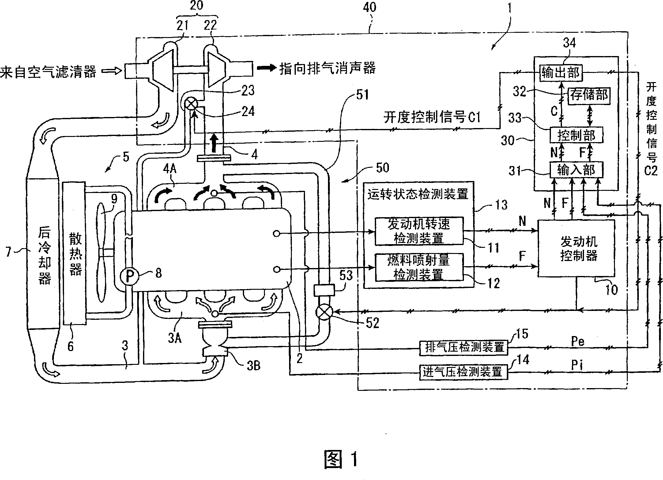
[0035] Fig. 1 is a schematic diagram showing a diesel engine (internal combustion engine) 1 according to a first embodiment of the present invention. In Fig. 1, a diesel engine 1 is equipped with: an engine main body 2, which is formed with a plurality of (four in this embodiment) combustion chambers; an intake pipeline 3, which supplies air to the combustion chambers; Exhaust gas is discharged to the outside of the combustion chamber; cooling mechanism 5, which is used to cool the diesel engine 1; engine controller 10, which controls the action of the engine body 2; intake air compression; exhaust gas recirculation system 50 for NO X Reduction of emissions (sometimes referred to as "exhaust gas recirculation").
[0036] An intake manifold 3A is installed between the intake line 3 and the engine body 2 so as to distribute the intake air from the intake line 3 to the respective combustion chambers. An intake pressure detection device 14 such as a sensor for detecting an intak...
no. 2 example
[0071] 4 and 5 are schematic diagrams of a diesel engine 1 having an air intake control device 40 according to a second embodiment of the present invention and a flowchart showing the function of the intake air control device 40 .
[0072] This embodiment differs greatly from the first embodiment in that the bypass passage 23 and the bypass valve 24 shown in FIG. 1 are not provided. Therefore, the opening control signal C2 is configured to be output only from the output unit 34 of the valve controller 30 to the EGR valve 52 . The output timing of the opening control signal C2 is shown in FIG. 5 , which is at S4 and S5 . About S1-S4, it is the same as the first embodiment.
[0073] In short, in this embodiment, when the control unit 33 of the valve controller 30 determines that the diesel engine 1 is rapidly decelerating from the medium-high speed and medium-to-high load operation state, the EGR valve 52 is fully opened to allow the intake air to flow from the side of the inta...
no. 3 example
[0078] 6 and 7 are schematic diagrams of a diesel engine 1 equipped with an air intake control device 40 according to a third embodiment of the present invention and a flowchart showing the operation of the intake air control device 40 .
[0079] This embodiment is greatly different from the first embodiment in that no EGR system 50 is provided as shown in FIG. 1 . Therefore, the opening control signal C1 is configured to be output only from the output unit 34 of the valve controller 30 to the bypass valve 24 . The timing of outputting the opening degree control signal C1 is in S5 and S6 as shown in FIG. 7 . Regarding S1 to S4, it is the same as the first embodiment.
[0080] In addition, the bypass passage 23 and the bypass valve 24 in this embodiment are dedicated devices for surge prevention and do not function as EGR.
[0081] Also in this embodiment constituted in this way, the surge at the time of sudden deceleration can be suppressed, and the same effect as that descr...
PUM
 Abstract
Description
Claims
Application Information