Melting method of converter, and facility for implementing the method

A converter and equipment technology, applied in non-ferrous metal smelting, ferroalloy production, and ferrous metal fields, can solve the problems of constant frequency value, negligible stirring effect, and not too good effect, etc.

Inactive Publication Date: 2007-10-10
YINGKOU DSMK TECH DEV
View PDF0 Cites 4 Cited by
  • Summary
  • Abstract
  • Description
  • Claims
  • Application Information

AI Technical Summary

Problems solved by technology

For subjects that require enhanced melt movement in the converter, the disadvantage of this method is that the melt movement caused by this method is in the opposite direction to the melt movement caused by the blown airflow
However, for solving other unresolved problems in converter production (increasing the output rate of molten steel, increasing the temperature of the melt and reducing the amount of dust), the disadvantage of this method is that it does not affect the vertical melt movement, Including the vertical melt motion in the peripheral space of the converter bath, which is extremely important, because the speed of the natural convective motion caused by the injection air flow near the furnace wall is greatly weakened, making the stirring effect in these parts negligible , which adversely affects various physical-chemical processes
[0004] The second disadvantage of the above method (and also the method of document [1]) is that the AC current generated by the power supply equipment used to cause the external magnetic field is either an industrial frequency current or a low frequency current, but they are all frequency constant current
However, for the problems raised by converter production, the effect of using alternating current with stable specifications, especially stable frequency, will not be very good

Method used


Image

  • Melting method of converter, and facility for implementing the method
  • Melting method of converter, and facility for implementing the method

Examples


Embodiment Construction

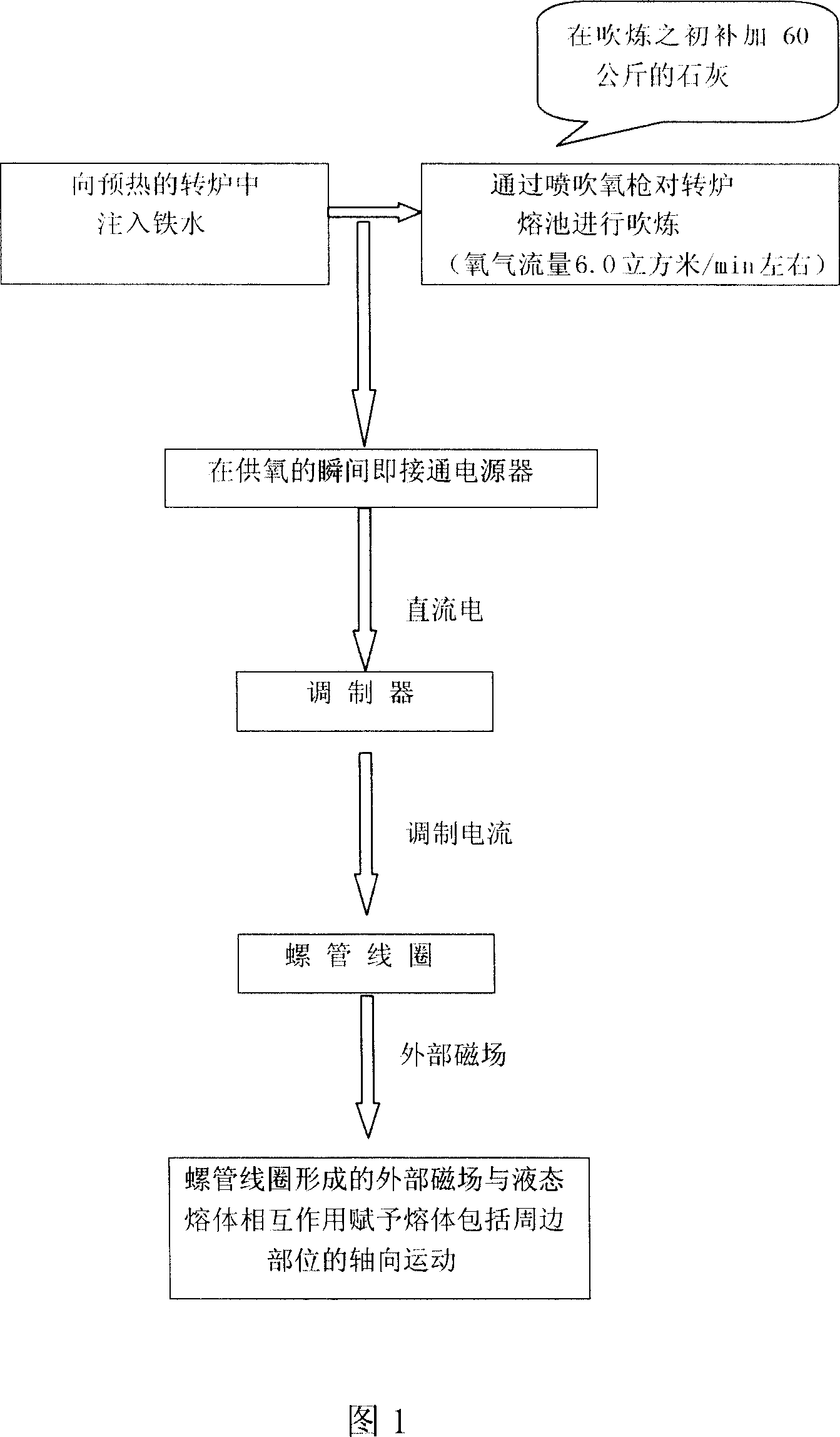
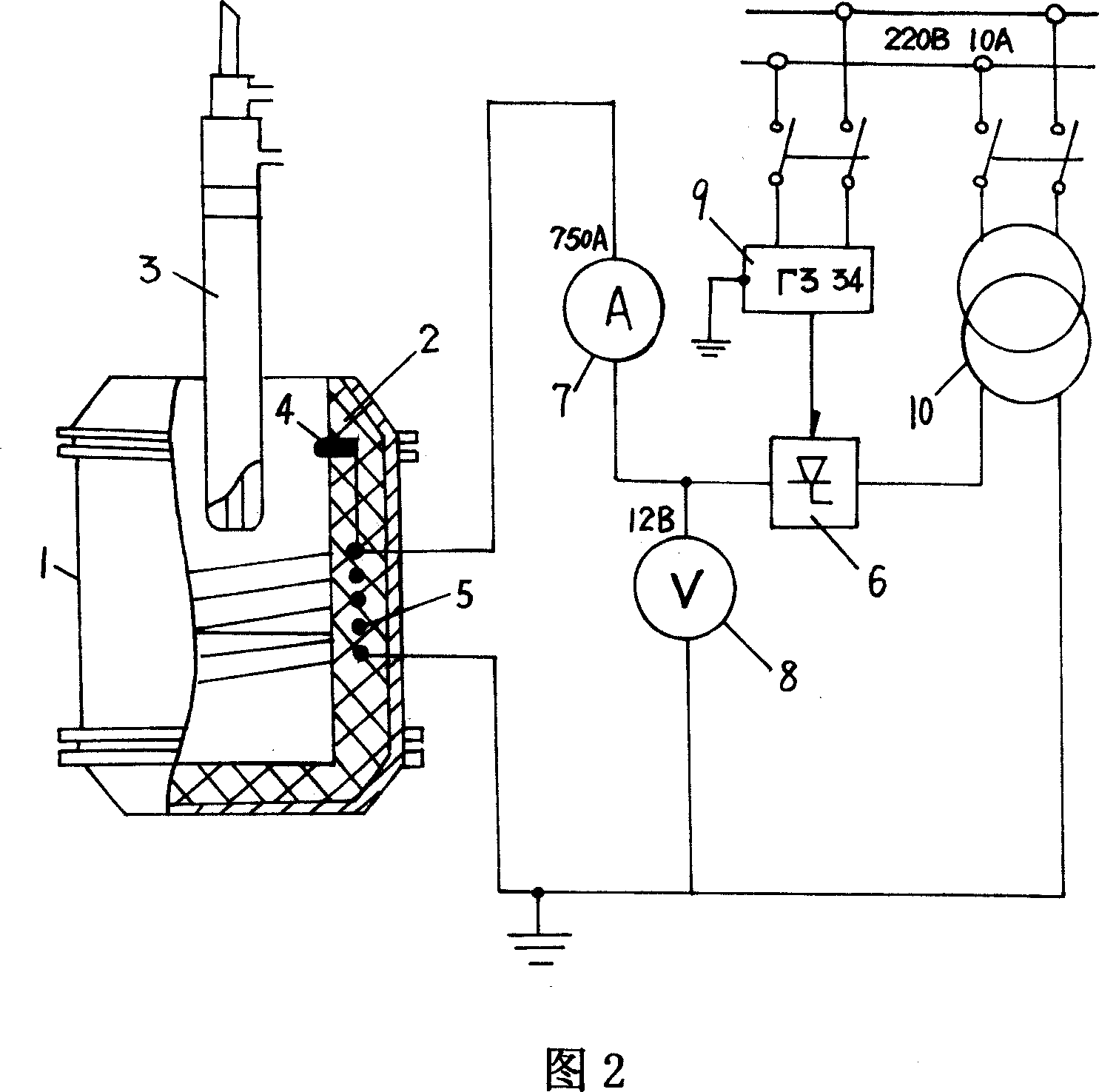
[0036]As shown in Figures 1 and 2, a converter smelting method is to establish a space magnetic field in the converter; provide the basic power required to establish the space magnetic field as direct current; pre-modulate the direct current before it acts on the space magnetic field forming end, To make the melt in the converter move from the periphery to the center. In actual operation, the solenoid coil fitted in the converter can be used to form a converter space magnetic field; the basic power supply for the solenoid coil is direct current; before the direct current is sent to the solenoid coil, it is pre-modulated, To make the melt in the converter move from the periphery to the center. In the invention, during the smelting process of the converter, iron-containing materials of 1-40 kg / ton of steel are added to the converter. The above-mentioned iron-containing material is ore, iron oxide scale, sintered ore, pellet ore or a mixture thereof. The present invention can a...


PUM


Abstract

This invention relates to method and apparatus for smelting ferrous metals, nonferrous metals and iron alloys in converter. The method provides DC to the converter to construct spacial magnetic field in the converter. The DC is pre-adjusted before applied to the converter so that the melt in the converter moves from the edge to the center of the converter. During converter smelting process, iron-containing raw material 1-40 kg/ton steel is added into the converter. The iron-containing raw material is selected from iron ore, oxide scale, pellet or other iron-containing raw materials. A supplementary magnetic field contrary to the direction of the ascending gas flow in the converter is formed by the contact electrode at the top of the converter. The apparatus comprises: a converter with refractory lining, an injection oxygen lance in the converter, a solenoidal coil in the lining, a DC generator, and a modulation signal generator.

Description

technical field [0001] The invention belongs to the fields of smelting of ferrous metals and nonferrous metals and ferroalloy production, and in particular relates to a converter smelting method and equipment for implementing the method. Background technique [0002] Ogurtsov A.N., Gles A.B. Continuous Casting of Steel - Dnepropetrovsk: Systematic Technology, 2002. - Page 675 - [Document 1] discloses the use of electromagnetic fields in continuous casting for crystallization tanks A method of axially stirring the inner metal, the purpose of which is to contain the rapid downward flow introduced by the middle ladle jet. For the subject that needs to strengthen the melt movement in the converter, the disadvantage of this method is that the melt movement caused by this method is opposite to the melt movement caused by the blowing air flow. The movement caused by the blowing air flow, according to Yawoyski B.N. The theory of steel production process—M.: Metallurgy, 1967—792 pag...

Claims


Application Information

Patent Timeline
Patent Type & Authority Applications(China)
IPC IPC(8): C21C5/28C21C5/42C21C5/46
Inventor 刘东业谢梅金C.И.波利亚科B.Ф.波尔沙科夫B.И.
Owner YINGKOU DSMK TECH DEV
Why Eureka
Try Eureka