Variable gain high sensitivity GPS receiver baseband frequency tracking method
A GPS signal and carrier tracking technology, used in instruments, measuring devices, satellite radio beacon positioning systems, etc., can solve problems such as carrier synchronization and bit synchronization difficulties, achieve simple, effective and easy to implement, improve receiving sensitivity, high GPS The effect of signal tracking
- Summary
- Abstract
- Description
- Claims
- Application Information
AI Technical Summary
Problems solved by technology
Method used
Image

Examples
Embodiment Construction
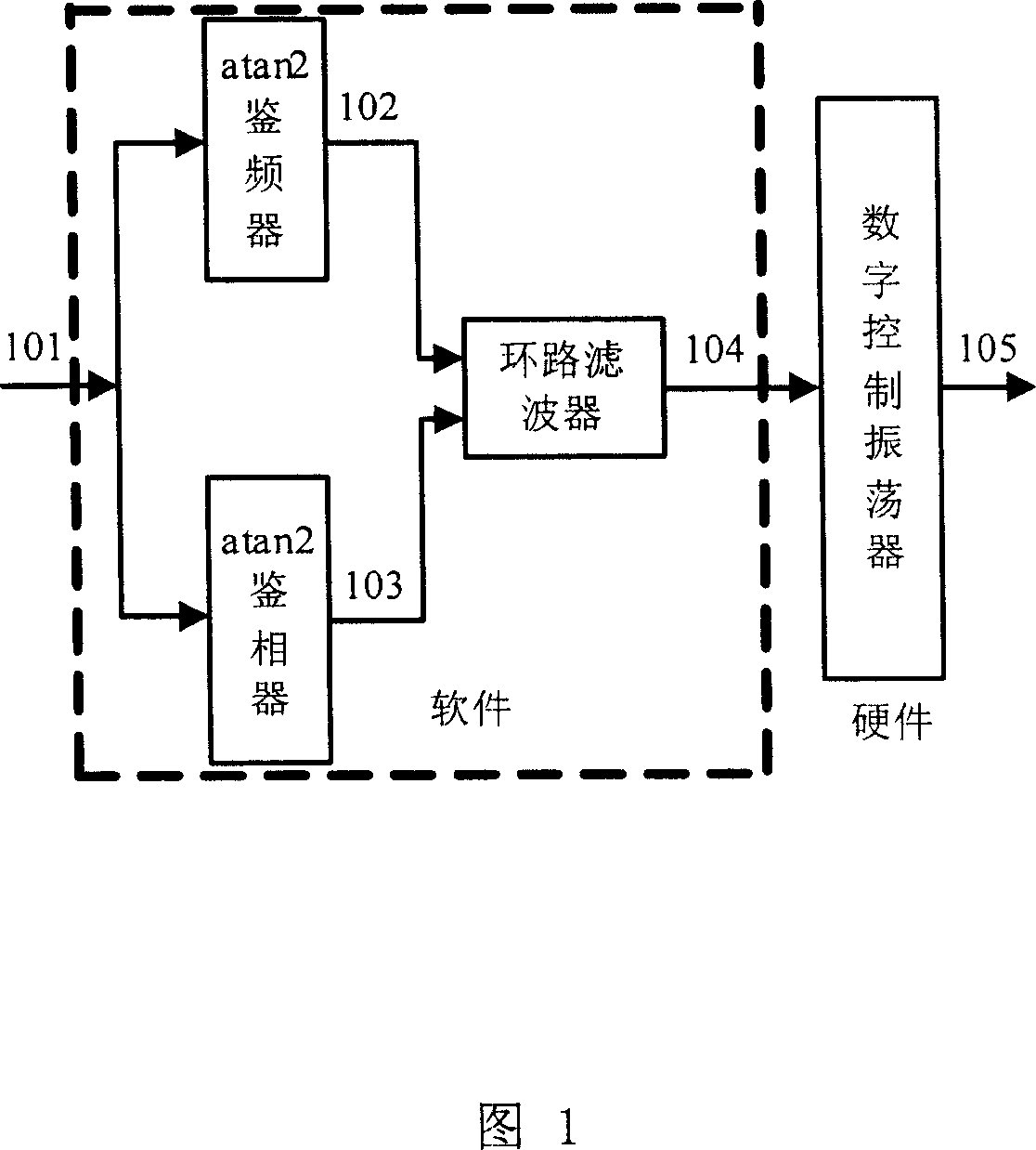
[0017] Fig. 1 is a block diagram of the carrier tracking loop in the present invention, and the meanings of the signals in the figure are as follows. 101 is the output of the Prompt correlator in the traditional GPS receiver, and the signal can be obtained from the hardware register by means of interrupt or software query. The new output value 101 of the correlator obtained each time is sent to a four-quadrant arctangent frequency detector and a four-quadrant arctangent phase detector respectively, and a frequency error estimation signal 102 and a phase error estimation signal 103 can be obtained respectively. 102 and 103 The control signal 104 of the digitally controlled oscillator is obtained after post-processing by the loop filter, which controls the frequency of the local reproduced carrier generated by the digitally controlled oscillator, and 105 is the output signal of the digitally controlled oscillator.
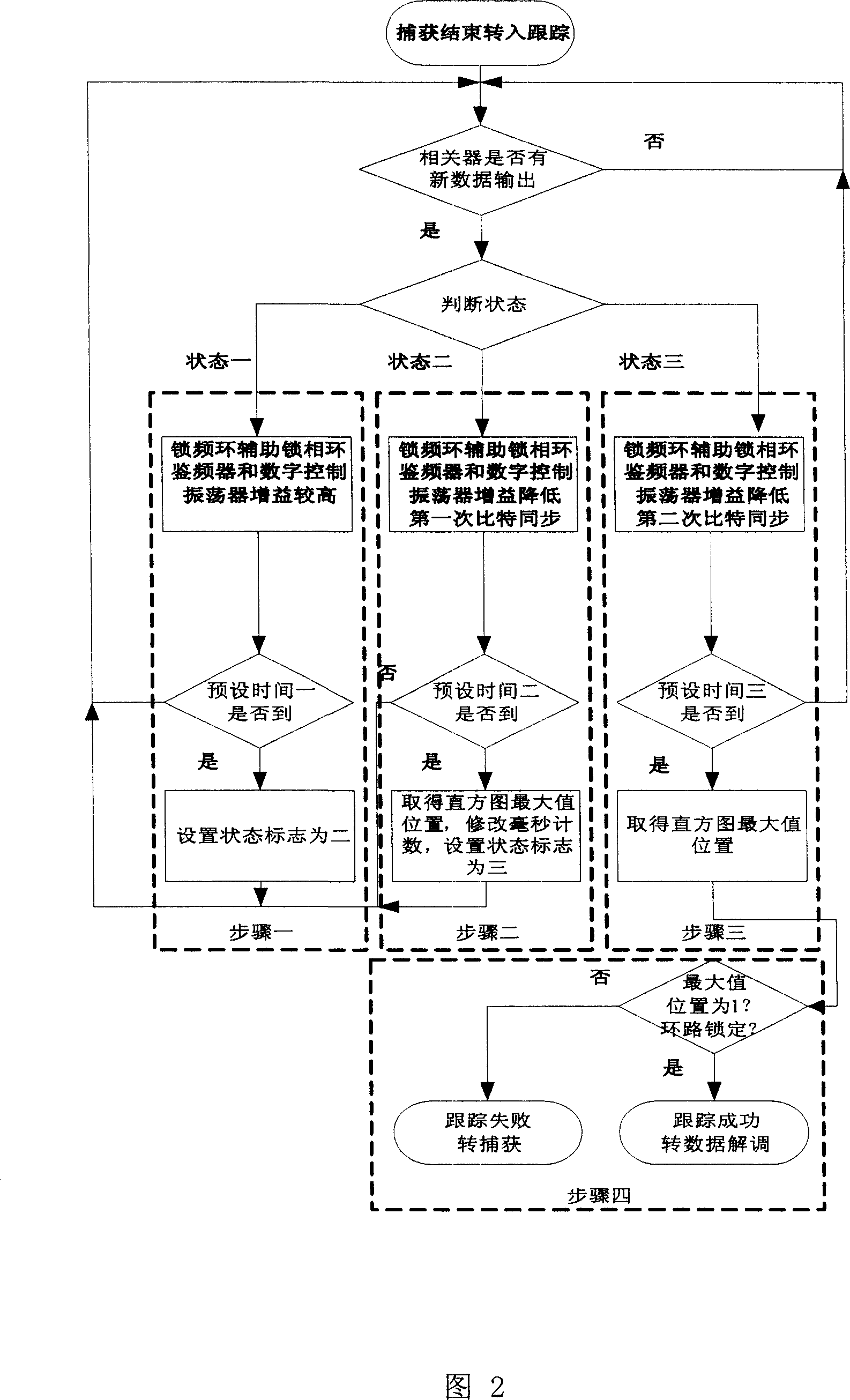
[0018] Fig. 2 is a schematic diagram of the method for tracking...
PUM
 Abstract
Description
Claims
Application Information