

Projector
A technology for projectors and projection optical systems, which is applied in the field of projectors and can solve problems such as complex structures, deterioration of quietness, and reduction of light spots
- Summary
- Abstract
- Description
- Claims
- Application Information
AI Technical Summary
Problems solved by technology
Method used
Image

Examples
no. 1 example 〕
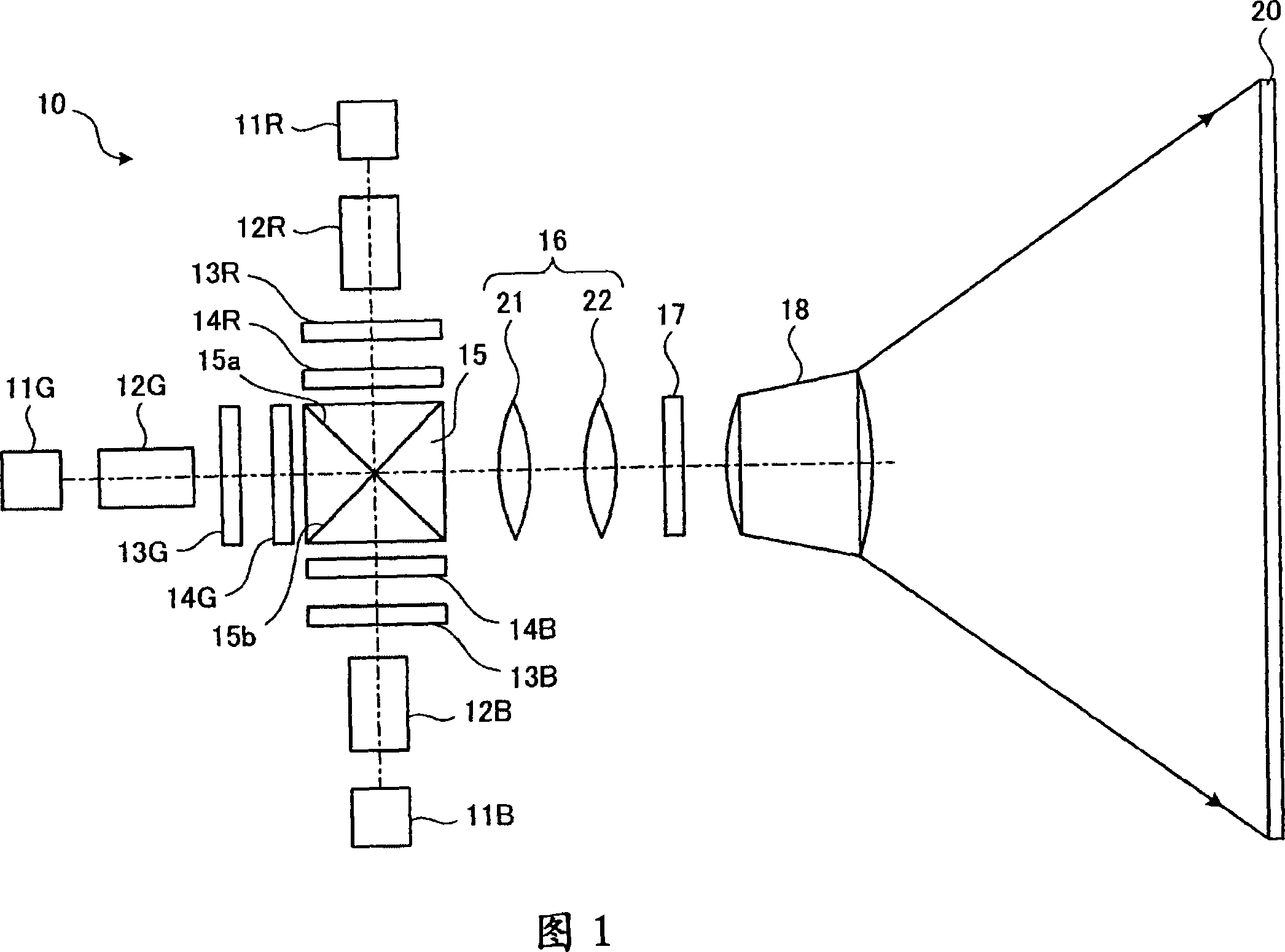
[0076] FIG. 1 shows a schematic configuration of a projector 10 according to a first embodiment of the present invention. The projector 10 is a so-called front projection type projector in which an image is viewed by supplying light to the screen 20 and observing the light reflected by the screen 20 . The projector 10 displays images using red laser light (hereinafter referred to as “R light”), green laser light (hereinafter referred to as “G light”), and blue light (hereinafter referred to as “B light”).
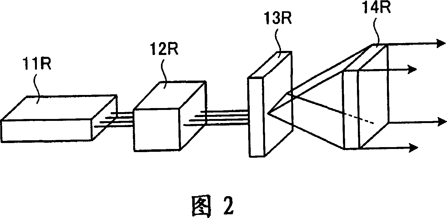
[0077] FIG. 2 shows a structure for supplying and modulating R light in the projector 10 . The light source unit 11R supplies four laser beams in the same or similar wavelength ranges. By using a plurality of laser beams, it is possible to supply a large amount of light. The light source unit 11R has four semiconductor lasers as solid-state light sources. In addition, as the light source unit 11R, a surface-emitting semiconductor laser in which four light emitting units ...
no. 2 example
[0110] FIG. 14 shows a schematic configuration of a projector 70 according to a second embodiment of the present invention. The projector 70 is characterized by having a micromirror array device 71 as a spatial light modulator. The same parts as those in the above-mentioned first embodiment are given the same symbols, and redundant explanations are omitted. The R light from the wavelength conversion element 12R enters the cross dichroic prism 15 via the diffractive optical element 13R. The G light from the wavelength conversion element 12G enters the cross dichroic prism 15 via the diffractive optical element 13G. The B light from the wavelength conversion element 12B enters the cross dichroic prism 15 via the diffractive optical element 13B. The cross dichroic prism 15 makes R light, G light, and B light incident on the micromirror array device 71 .
[0111] The micromirror array device 71 has a plurality of movable mirror elements (not shown) formed on the incident surfac...
no. 3 example
[0114] FIG. 15 shows a schematic configuration of a projector 80 according to a third embodiment of the present invention. The projector 80 has an optical scanning device 85 that scans the laser beams from the light source units 81R, 81G, and 81B. The same parts as those in the above-mentioned first embodiment are given the same symbols, and repeated explanations are omitted. The light scanning device 85 is an image forming unit that forms an image using laser light from the light source units 81R, 81G, and 81B.
[0115] The R-light light source unit 81R supplies the R-light modulated according to the image signal. The G-light light source unit 81G supplies G-light modulated according to an image signal. The B-light light source unit 81B supplies the B-light modulated according to the image signal. Any of amplitude modulation and pulse width modulation can be used for modulation corresponding to the image signal. Each of the light source units 81R, 81G, and 81B has a semic...
PUM
| Property | Measurement | Unit |
|---|---|---|
| diameter | aaaaa | aaaaa |
Abstract
Description
Claims
Application Information