
Cutting tool for metal working and method for producing it

A cutting tool and metal processing technology, applied in the field of tool holder body, can solve the problem of not bringing about the fatigue strength of the tool holder body

Inactive Publication Date: 2007-10-17
SANDVIK INTELLECTUAL PROPERTY AB
View PDF2 Cites 12 Cited by
  • Summary
  • Abstract
  • Description
  • Claims
  • Application Information

AI Technical Summary

Problems solved by technology

However, it has proven that this method does not lead to a satisfactory fatigue strength of the tool holder body in the case of particularly high loads, for example in the case of the material exceeding the yield point of 60% in tension

Method used


Image

  • Cutting tool for metal working and method for producing it
  • Cutting tool for metal working and method for producing it
  • Cutting tool for metal working and method for producing it

Examples


example 1

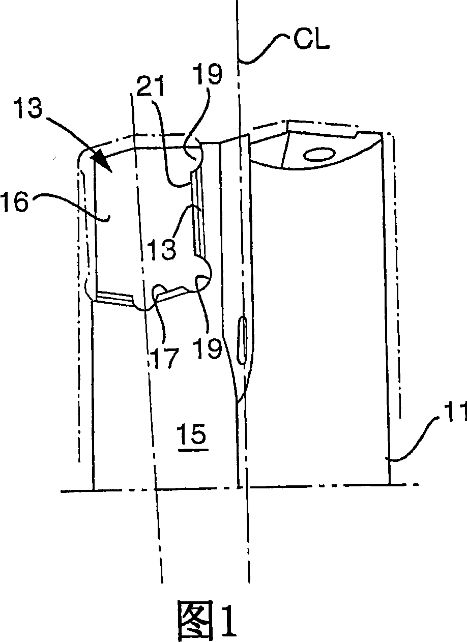
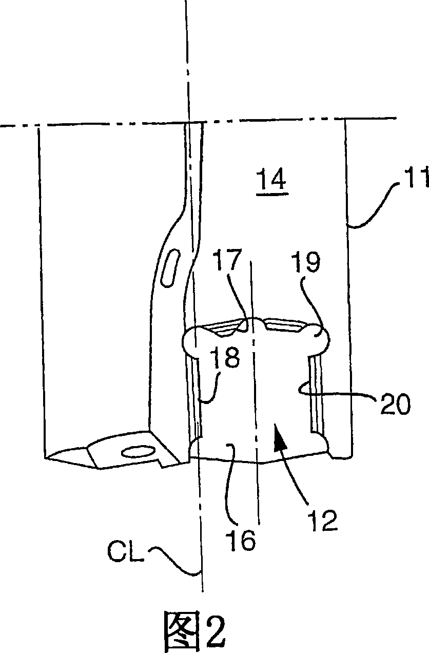
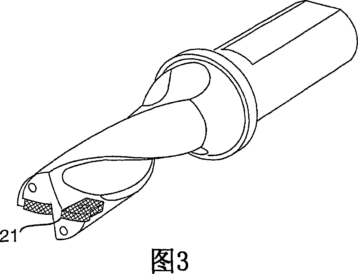
[0034] Tool steel SS2242 was prepared to the final shape and dimensions of the indexable short hole drill bit according to the present invention. The drill is deep hardened by heating to 960°C followed by air quenching, giving the tool a 1520N / mm 2 The yield point under tension and has a hardness of 50HRC. Subsequently, the entire holder body of the tool is shot peened under the following conditions:

[0035] Angle of incidence: 90 degrees relative to the longitudinal axis of the drill bit

[0036] Distance between nozzle and tool holder body: 100mm

[0037] Rotation speed of tool holder body: 30rev / min

[0038] Time: 60s

[0039] Medium: 52HRC round steel ball, 0.20mm

[0040] Adjust the pressure and flow to achieve an Almen value of 18A

example 2

[0042] Example 1 was repeated, and in addition to hardening a nitrocarburizing treatment as disclosed in US 2005 / 0002744 was performed.

example 3

[0044]The tool holder bodies of Examples 1 and 2 with cutting inserts made of cemented carbide were tested in a short hole drilling operation at a depth of 60 mm. Drill holes in the material SS2541300HB, the cutting data is: 200m / min speed and 0.20mm / rev feed rate. These cutting data yield the force at which the material yields and stretches 85%. As a further reference, the same type of deep-hardened and cold-work-blackened drill bit was tested as commercially available. The tool life is based on the damage of the tool holder body.

[0045] result:

[0046] Refer to 300m

[0047] Example 2 50m

[0048] Example 1 >1000m


PUM

PropertyMeasurementUnit
densityaaaaaaaaaa
diameteraaaaaaaaaa

Abstract

According to the invention, there is provided a cutting tool and a method in the production of a cutting tool for metalworking that results in a holder body having increased fatigue strength at loads over 60 % of the yield point in tension. The method and the tool are characterized in that the holder body of the tool is subjected to a hardening process resulting in deep hardening, and that the holder body then is subjected to a surface treatment resulting in a strain hardening of the surface in order to introduce compressive stresses in the surface zone of the holder body.

Description

technical field [0001] The invention relates to a cutting tool for metalworking and to a method of producing a cutting tool, for example a tool holder body with one or more insert seats for indexable inserts. Examples of such tools are drills with a plurality of cutting inserts made of cemented carbide, cermet or ceramic. Background technique [0002] Cutting tools for chip removal in metallic materials, for example, come in many different varieties, including tools for drilling, grinding and turning. Common to these tools is that they generally include a tool holder body and one or more cutting inserts housed in insert seats within the tool holder body. Usually, the toolholder body is made of hardened steel and subsequently blackened in cold working, obtaining a black surface, and the cutting inserts are made of carbide, cermet or ceramic. [0003] The static and dynamic loads acting on tools for cutting metal materials are becoming increasingly higher. Increased loads r...

Claims


Application Information

Patent Timeline
Patent Type & Authority Applications(China)
IPC IPC(8): C21D9/22B23B27/00B23B29/04B23B29/24
CPCB23P9/00C21D9/22C21D7/06B23P15/28C21D1/06B23B51/04B23B27/00B23B29/04B23B29/00B23B29/24B23C5/16
Inventor 克拉斯·蒂宾戈罗格·隆格伦丹·霍格隆德
Owner SANDVIK INTELLECTUAL PROPERTY AB
Learn More