
High efficiency chilled high intensification piston of diesel engine

A diesel engine and piston technology, which is applied in the field of high-strength diesel engine pistons, can solve the problems of affecting the cooling effect, misalignment, and obstruction of lubricating oil flowing into the oil chamber, so as to improve the oil supply efficiency, ensure the working reliability, and improve the cooling effect.

Inactive Publication Date: 2007-10-31
YANGDONG CO LTD
View PDF0 Cites 2 Cited by
  • Summary
  • Abstract
  • Description
  • Claims
  • Application Information

AI Technical Summary

Problems solved by technology

[0003] The existing internal cooling oil chamber is an annular oil passage located inside the piston, below the combustion chamber, and parallel to the top of the piston. The wall of the oil chamber facing the oil inlet hole is an arc-shaped concave surface. When rushing to the oil cavity vertically, the arc-shaped concave surface forms a strong reflection of the lubricating oil, resulting in a large obstacle to the flow of the lubricating oil into the oil cavity, thereby reducing the oil supply efficiency to the internal cooling oil cavity and affecting the cooling effect
In addition, at present, more than 95% of domestic diesel engines use two valves for air distribution, and the center of the combustion chamber on the piston does not coincide with the center of the piston, which will lead to uneven heat transfer
Seen from the projection direction of the top surface of the piston, which side the combustion chamber is inclined to, the heat load on that side is relatively serious, and the existing internal cooling oil chamber cannot control the oil distribution on both sides of the oil inlet hole, so the cooling of the piston is not good. Uniformity also directly affects the cooling effect

Method used


Image

  • High efficiency chilled high intensification piston of diesel engine
  • High efficiency chilled high intensification piston of diesel engine
  • High efficiency chilled high intensification piston of diesel engine

Examples


example 1

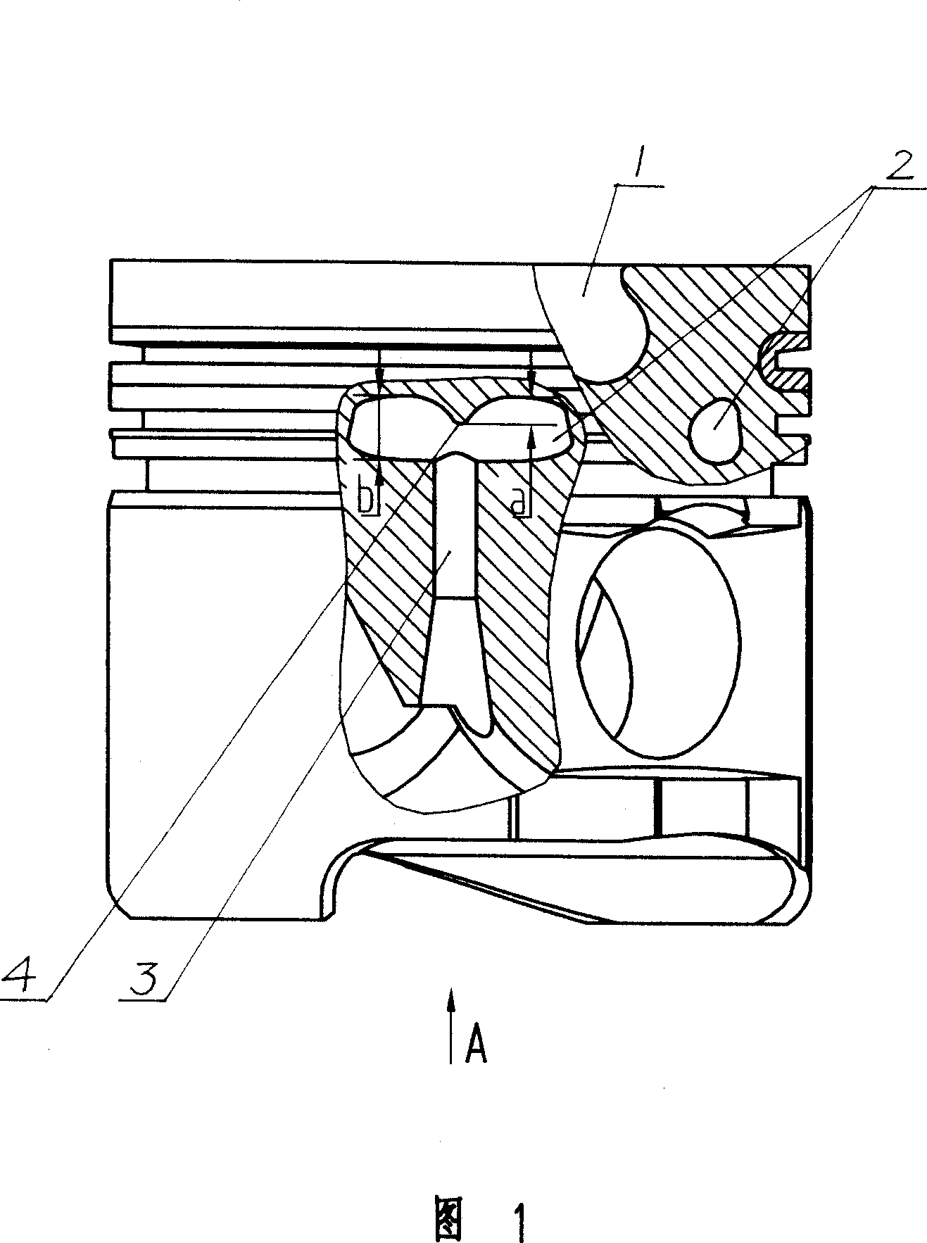
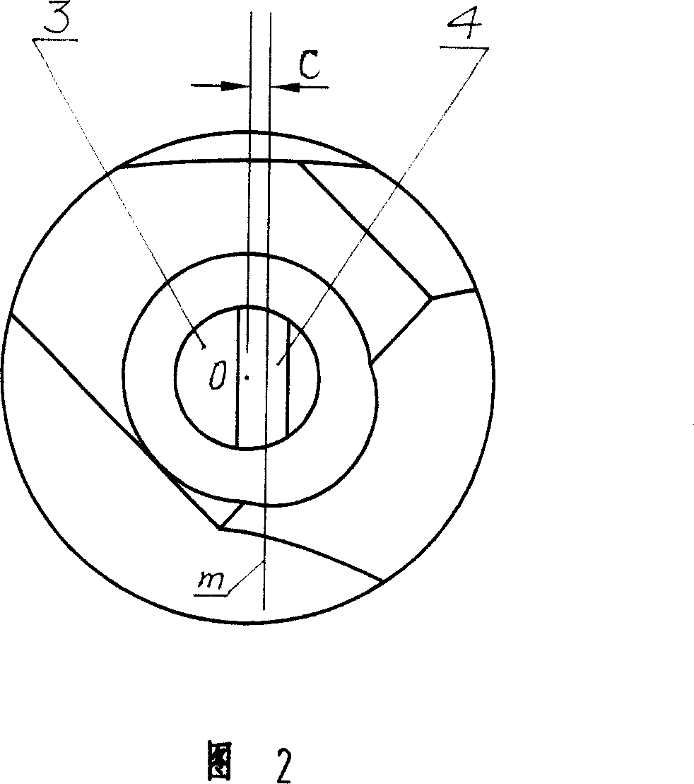
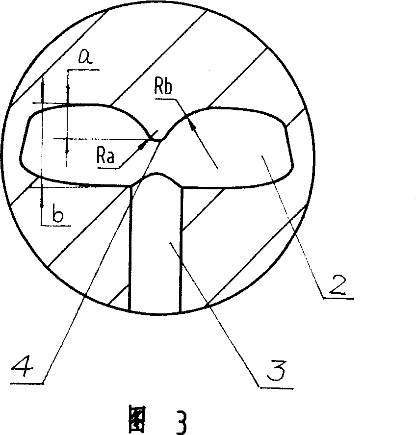
[0013] Example 1: Referring to Figures 1, 2, and 3, the high-efficiency cooling high-strength diesel engine piston has an annular internal cooling oil chamber 2 located below the combustion chamber 1, and one side of the bottom of the piston has an axial shaft communicating with the internal cooling oil chamber. There is an oil inlet hole 3 and an oil return hole on the other side. In the inner cooling oil chamber facing the oil inlet hole, there is a shunt protrusion 4 along the radial direction of the piston. The fillet radius Ra of the shunt protrusion is 1.5mm. The height a of the convex point is 1 / 4 times of the height b of the oil cavity. The two sides of the cross section of the convex point are arc lines, and the radius Rb of the arc is 10mm. The center of the convex point ridge area is the center of the rounded corner of the convex point. The straight line m where the projected line segment of the line segment is relative to the piston top plane deviates from the cente...


PUM


Abstract

A highly effective cooling highly-reinforced diesel engine piston is provided with an annular oil cavity on lower portion of a burning chamber in the piston, wherein the position of the oil cavity relative to an oil inlet is provided with a distribution boss along the radial direction of the piston, and a projection line in the ridge center of the distribution boss relative to the top plate of the piston is positioned in the projection area in the top plate of the piston. The projection line has a bias value of 0-3mm as deviating to the oil inlet center, and the height of the boss is 1 / 8-3 / 4 of the height of the oil cavity, and two sides of the boss cross-section is a sloping line or an arcuate path, or a parabolic curve. The invention is used in the diesel engine with average effective pressure higher than 1. 3MPa and can enhance the oil-supplying efficiency of fluid oil efficiently, and also can control the oil flow distribution in two side oil cavities efficiently as the center of the burning chamber no reclosing with the center of the piston, thereby cooling the piston evenly and enhancing the cooling effect.

Description

technical field [0001] The invention relates to a diesel engine piston, in particular to a high-efficiency cooling high-strength diesel engine piston. Background technique [0002] Due to the continuous improvement of the degree of strengthening of diesel engines, the mechanical load and thermal load of the pistons of diesel engines are increasing. Therefore, appropriate measures must be taken to cool the pistons, reduce the temperature of the pistons in time, and improve the reliability of the pistons. It is generally believed that when the average effective pressure of the diesel engine is greater than 0.85Mpa, the piston must be specially cooled. For high-strength diesel engines with an average effective pressure exceeding 1.3Mpa, or when the cylinder bore is large, the use of free jet cooling can no longer meet the requirements, and the internal cooling oil chamber must be used for forced cooling. [0003] The existing internal cooling oil chamber is an annular oil pass...

Claims


Application Information

Patent Timeline
Patent Type & Authority Applications(China)
IPC IPC(8): F02F3/22
Inventor 杨勇佳陈伟
Owner YANGDONG CO LTD
Learn More