Composite optical system for solar sensor and realizing method thereof

A solar sensor and optical system technology, applied in the field of solar sensors, can solve problems such as small hole blockage or pollution, and achieve the effect of avoiding blockage or pollution and high positioning accuracy

Inactive Publication Date: 2007-11-07
BEIHANG UNIV
View PDF1 Cites 9 Cited by
  • Summary
  • Abstract
  • Description
  • Claims
  • Application Information

AI Technical Summary

Problems solved by technology

Moreover, in practical applications, because the pore size is too small, it is easy to cause the small pores to be blocked or polluted.

Method used


Image

  • Composite optical system for solar sensor and realizing method thereof
  • Composite optical system for solar sensor and realizing method thereof
  • Composite optical system for solar sensor and realizing method thereof

Examples


Embodiment Construction

[0023] The present invention will be further described in detail below in conjunction with the accompanying drawings and specific embodiments.

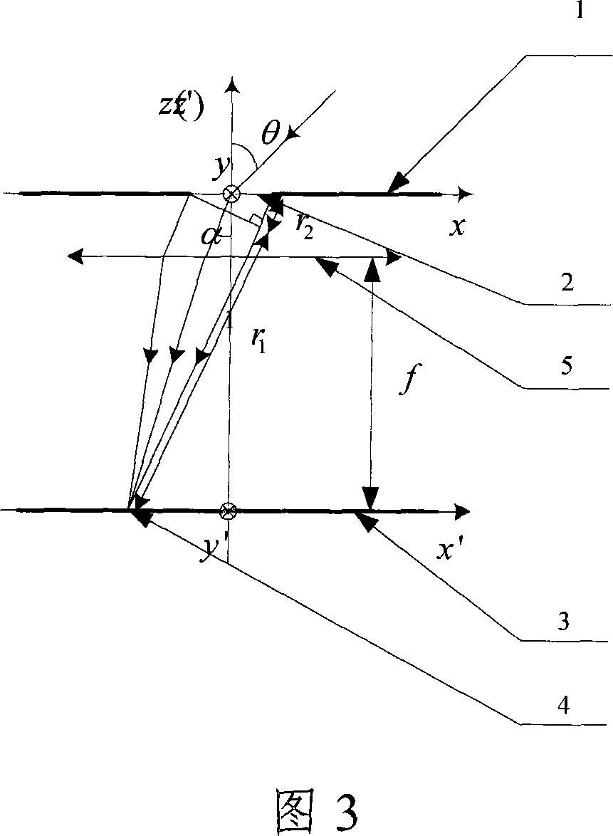
[0024] The invention solves the problem that the existing solar sensor optical system is difficult to form smaller diffraction spots by providing a composite optical system of the solar sensor. The key of the composite optical system of the present invention is to arrange a microlens opposite to the small hole of the optical mask at the rear of the optical mask along the incident light direction.

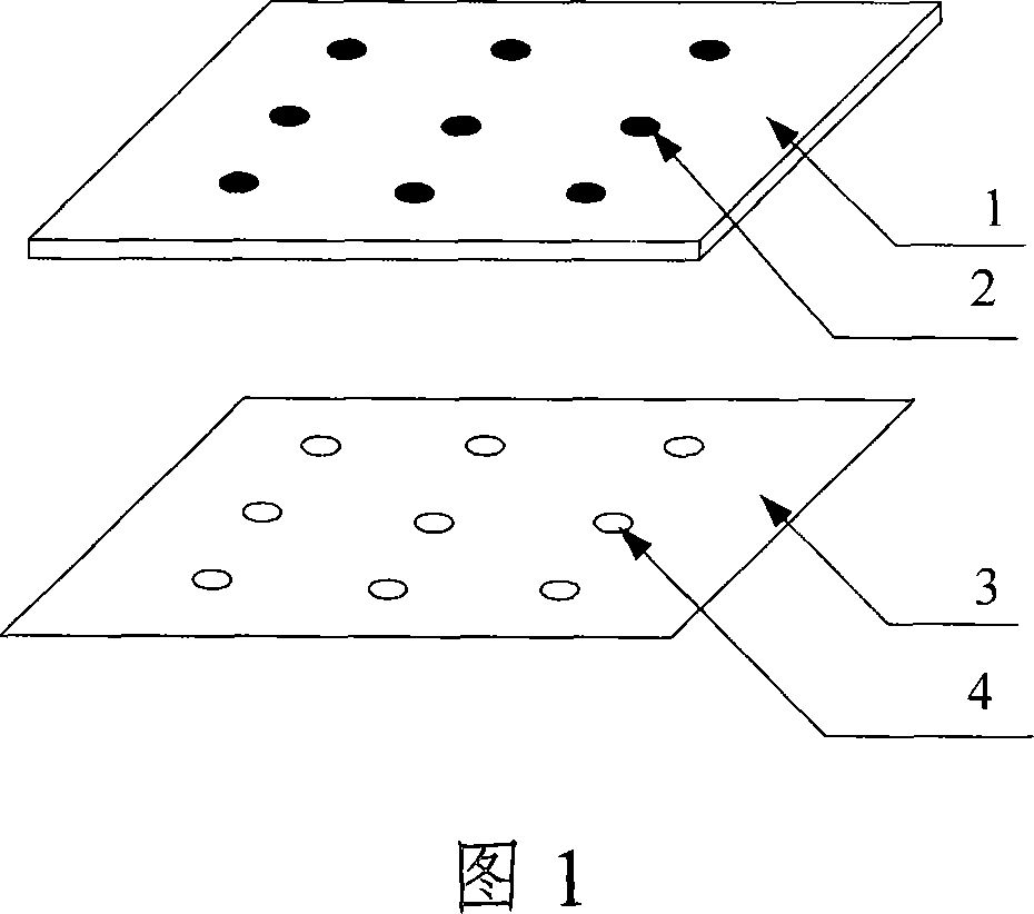
[0025] The composite optical system of the present invention and the structure of the photosensitive imaging surface are as shown in Figure 2, the composite optical system includes: an optical mask 1 and a microlens 5 provided with a small hole 2, and the microlens 5 is arranged on the optical mask 1 The rear part along the incident light direction is opposite to the small hole 2 on the optical mask 1 . Sunlight, which is approximately par...


PUM


Abstract

The invention discloses a combined optical system for a sun sensor, comprising photomask and microlens, where the photomask is equipped with pore, and the microlens is arranged in back of the photomask in the direction of incident light and opposite to the pore. And the invention discloses a method for implementing the combined optical system. And the invention can provide smaller diffraction facula by bigger pore and is beneficial to preventing the pore on the photomask from being stopped or polluted.

Description

technical field [0001] The invention relates to the sun sensor technology in celestial navigation, in particular to a composite optical system in the sun sensor and its realization method. Background technique [0002] The sun sensor is an attitude sensor that measures the angle between the sun's line of sight and a certain body axis or coordinate plane of a spacecraft such as a satellite, using the sun as the reference azimuth. The sun sensor mainly has several types such as "0-1" type, analog type, coded type and digital type. Among them, the digital sun sensor is a new generation of sun sensor based on a charge coupled device (CCD, Charge Coupled Device), or an active pixel sensor complementary metal oxide semiconductor (APS CMOS, Active Pixel Sensor Complementary Metal-Oxide Semiconductor) image sensor , which can meet the requirements of high precision, miniaturization and low power consumption for the attitude sensor of micro-spacecraft, and become one of the most pro...

Claims


Application Information

Patent Timeline
Patent Type & Authority Applications(China)
IPC IPC(8): G01C17/34G02B3/00
Inventor 张广军江洁温志明樊巧云
Owner BEIHANG UNIV
Why Eureka
Try Eureka