High-efficiency single-phase and three-phase grid-connected generating system

A high-efficiency, three-phase technology, used in photovoltaic power generation, single-grid parallel feeding arrangements, current collectors, etc., can solve the problems of low system efficiency, many consumables, and high conduction loss of power switching devices

Inactive Publication Date: 2007-11-14
SHANGHAI UNIV +1
View PDF0 Cites 23 Cited by
  • Summary
  • Abstract
  • Description
  • Claims
  • Application Information

AI Technical Summary

Problems solved by technology

[0002] The "Current Type Photovoltaic Grid-connected System and Its Control Device" that the applicant applied for earlier provides a grid-connected system that uses high-frequency inductors and high-frequency transformers to replace the power-frequency inductors in traditional current-source photovoltaic grid-connected systems. And power frequency transformers, although they have overcome the shortcomings of traditional power frequency inductors and power frequency transformers such as large volume, many consumables, large losses, high cost, and poor harmonic suppression ability, there are still a large number of power transistors, and the power in the process of energy transfer The high conduction loss of the switching device leads to the problem that the system efficiency is not high enough

Method used


Image

  • High-efficiency single-phase and three-phase grid-connected generating system
  • High-efficiency single-phase and three-phase grid-connected generating system
  • High-efficiency single-phase and three-phase grid-connected generating system

Examples


Embodiment 1

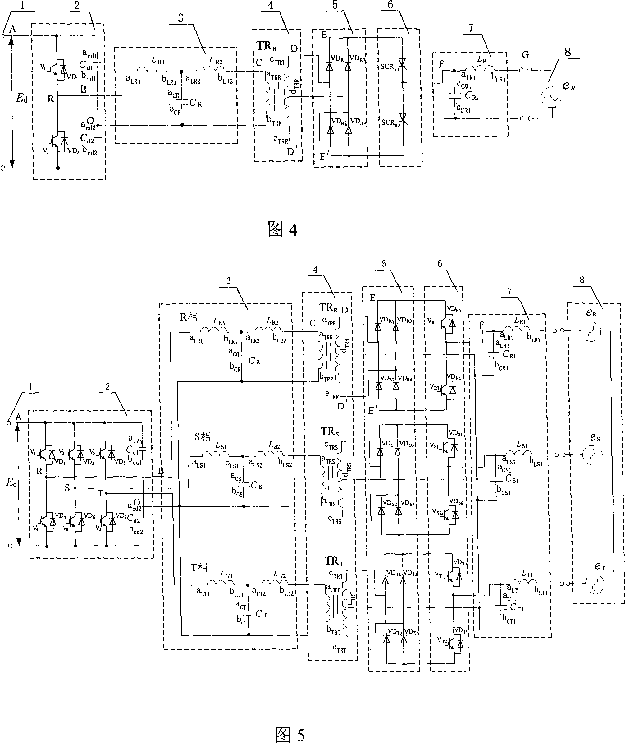
[0031] Embodiment 1: (single-phase grid-connected system, see Fig. 3, Fig. 4)

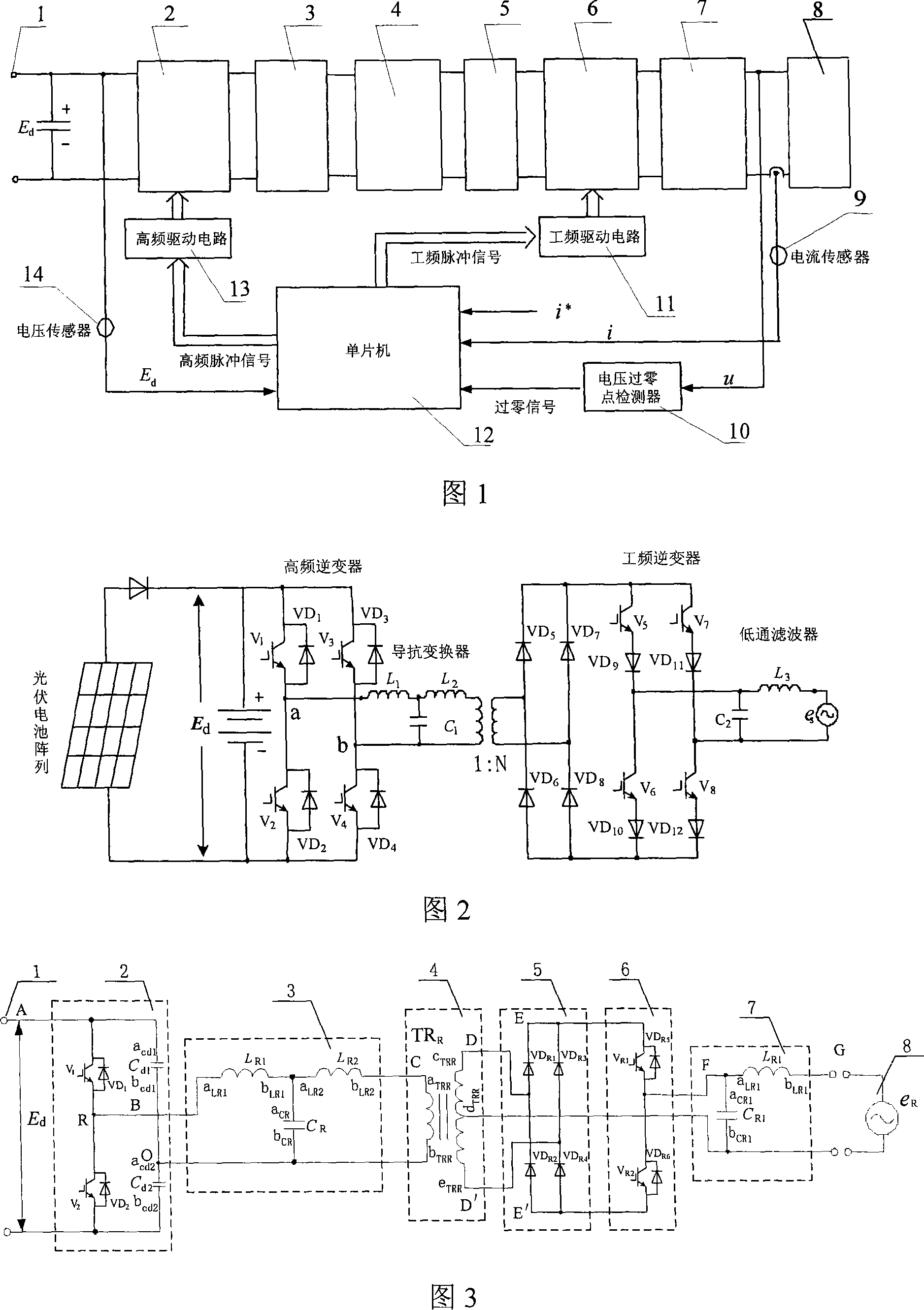
[0032]This high-efficiency single-phase grid-connected power generation system is composed of high-frequency inverter 2, impedance converter 3, high-frequency transformer 4, high-frequency rectifier 5, power frequency inverter 6 and low-pass filter 7, and its characteristics The structure of the high-frequency inverter 2 is: the anode of the photovoltaic cell array 1 is connected to the power transistor V 1 The collector (drain) and capacitance C d1 the a cd1 Terminal, the negative pole of the photovoltaic cell array 1 is connected to the power transistor V 2 The emitter (source) and capacitance C d2 the b cd2 terminal, the power transistor V 1 The emitter (source) of the power transistor is connected to V 2 collector (drain) and output to an input terminal of the impedance converter 3, the capacitor C d1 the b cd1 connected to the capacitor C d2 the a cd2 terminal and output to the other...

Embodiment 2

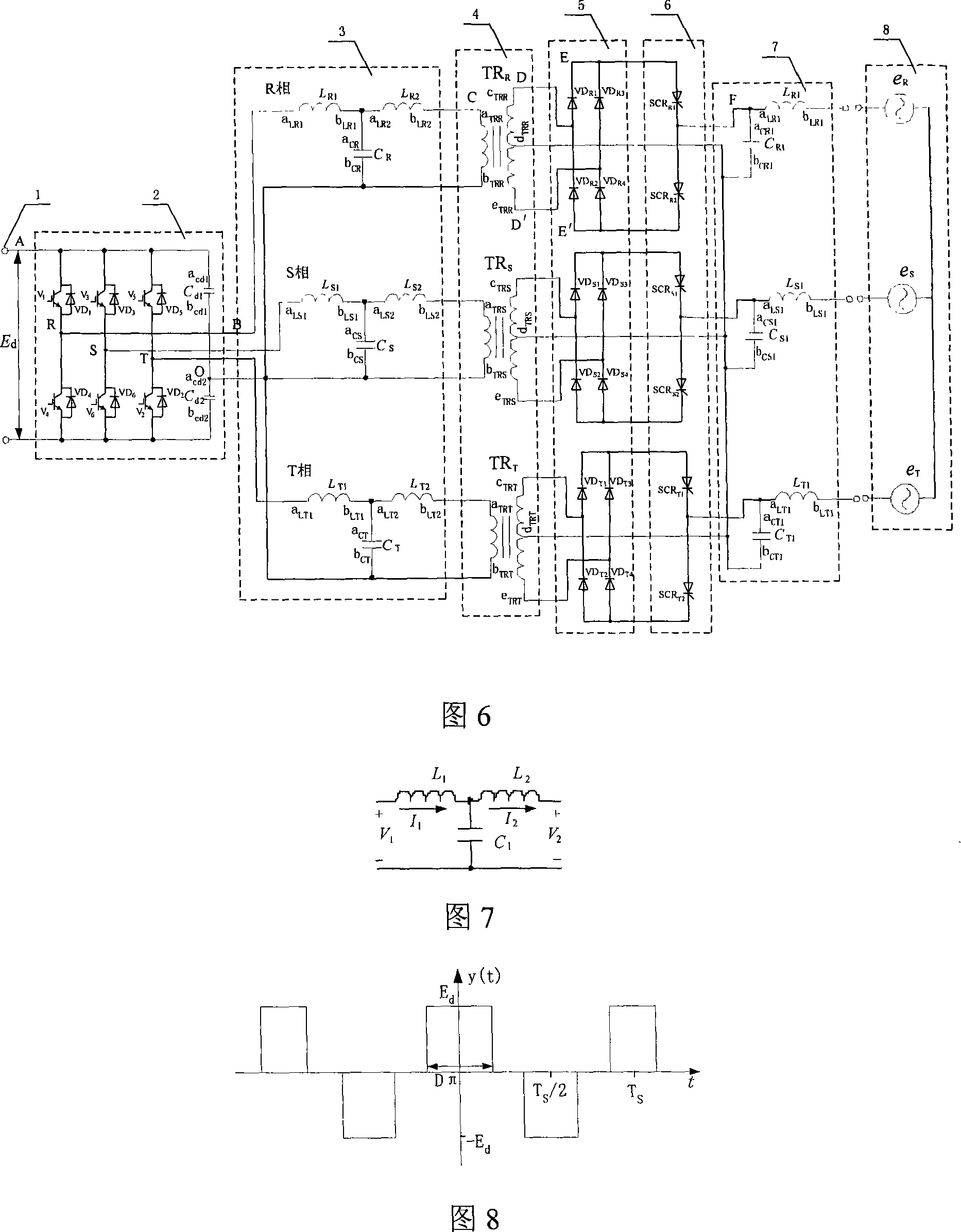
[0038] Embodiment 2: (three-phase grid-connected system, see Fig. 5, Fig. 6)

[0039] This high-efficiency three-phase grid-connected power generation system is composed of high-frequency inverter 2, impedance converter 3, high-frequency transformer 4, high-frequency rectifier 5, power frequency inverter 6 and low-pass filter 7, and its characteristics The structure of the high-frequency inverter 2 is: the anode of the photovoltaic cell array 1 is connected to the power transistor V 1 The collector (drain), power transistor V 3 The collector (drain), power transistor V 5 The collector (drain) and capacitance C d1 the a cd1 Terminal, the negative pole of the photovoltaic cell array 1 is connected to the power transistor V 4 The emitter (source), power transistor V 6 The emitter (source), power transistor V 2 The emitter (source) and capacitance C d2 the b cd2 terminal, the power transistor V 1 The emitter (source) of the power transistor is connected to V 4 collector ...


PUM


Abstract

This invention relates to a high efficiency single-phase and the three-phase incorporation generating system. This incorporation generating system is composed by the high frequency inverter, immittance convertor, high-frequency transformer, high frequency rectifier, power frequency inverter, lowpass filter, voltage zero crossing detector, high frequency drive circuit and power frequency drive circuit. This system counter turn the direct voltage which are gained by light battery array, fuel cell, windpower generation and other methods to high-frequency voltage and input immittance convertor. The high-frequency current output by immittance convertor is merged into single-phase or three-phase electric network olationand by the high-frequency transformer, ranking transformed by electric current, commutated by the high frequency rectifier, counter turned by the power frequency inverter and filtered by lowpass filter. By improving the system topology, reducing the power transistor number, this invention not only reduces the cost, realize installment miniaturization, but also reduces the power loss in the energy transfer process.

Description

technical field [0001] The invention relates to a high-efficiency single-phase and three-phase grid-connected power generation system. Background technique [0002] The "Current Type Photovoltaic Grid-connected System and Its Control Device" that the applicant applied for earlier provides a grid-connected system that uses high-frequency inductors and high-frequency transformers to replace the power-frequency inductors in traditional current-source photovoltaic grid-connected systems. And power frequency transformers, although they have overcome the shortcomings of traditional power frequency inductors and power frequency transformers such as large volume, many consumables, large losses, high cost, and poor harmonic suppression ability, there are still a large number of power transistors, and the power in the process of energy transfer The high conduction loss of the switching device leads to the problem that the system efficiency is not high enough. Contents of the inventi...

Claims


Application Information

Patent Timeline
Patent Type & Authority Applications(China)
IPC IPC(8): H02J3/38H02J7/35
CPCY02E10/566Y02E10/563Y02E10/56
Inventor 陈国呈吴春华孙承波周勤利
Owner SHANGHAI UNIV
Why Eureka
Try Eureka