Ceramic filter-element dust collector

A technology of ceramic filter elements and dust collectors, which is applied in the direction of dispersed particle filtration, chemical instruments and methods, and separation of dispersed particles. Long service life and good filtering effect

A technology of ceramic filter elements and dust collectors, which is applied in the direction of dispersed particle filtration, chemical instruments and methods, and separation of dispersed particles. Long service life and good filtering effect

CN101073734AInactive Publication Date: 2007-11-21山西金色阳光环保工程有限公司

Image

  • Ceramic filter-element dust collector
  • Ceramic filter-element dust collector
  • Ceramic filter-element dust collector

Examples


Embodiment Construction

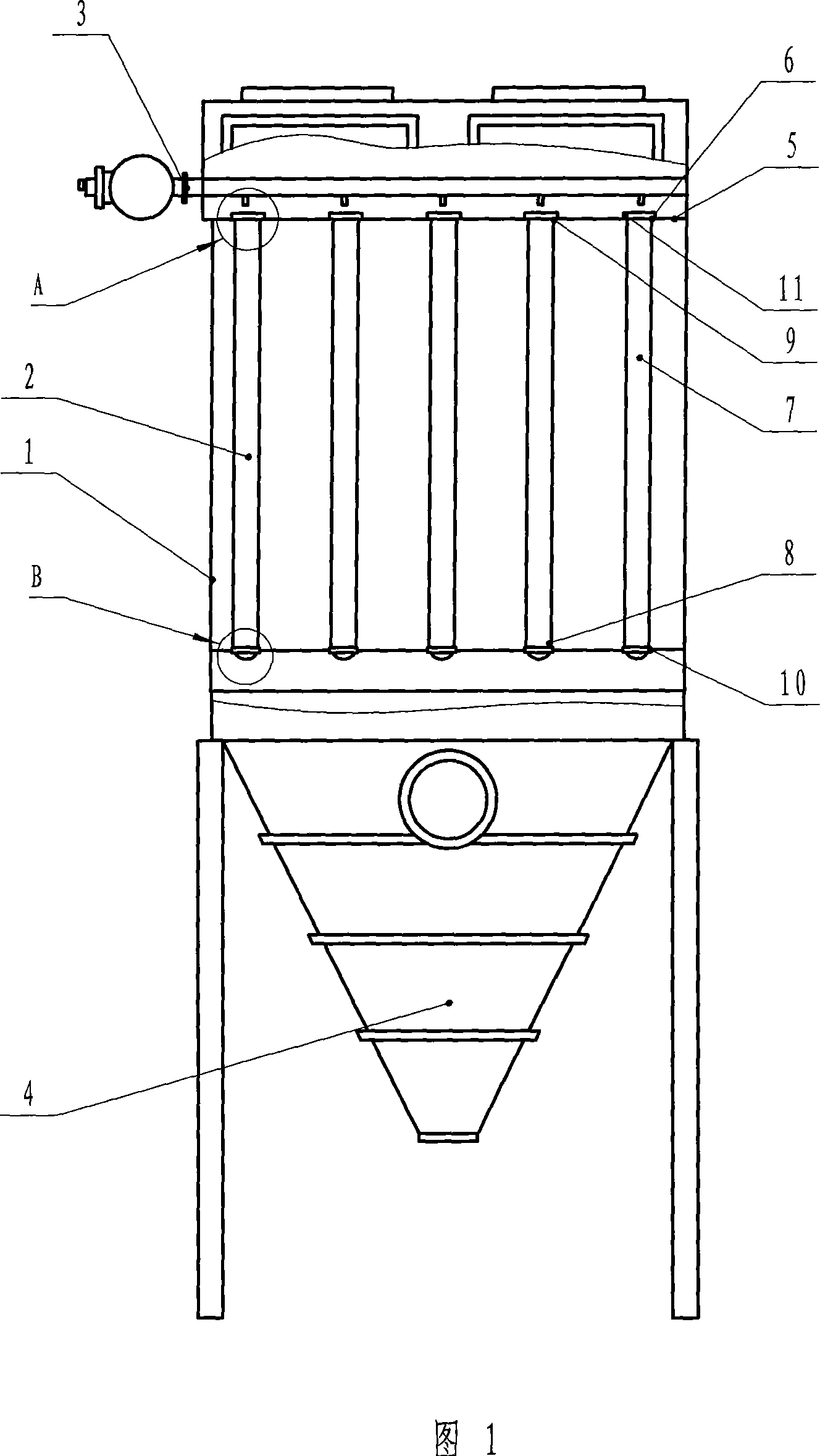
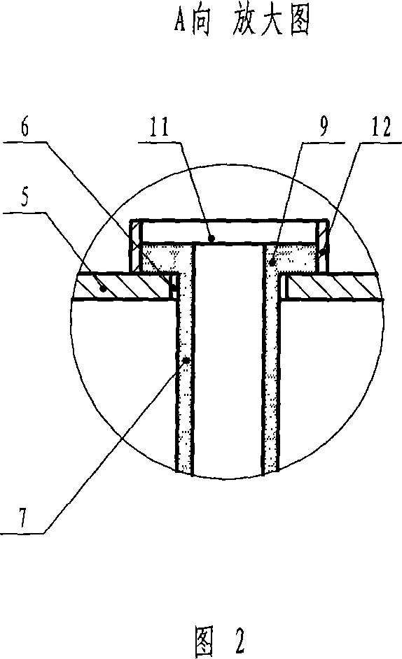
[0021] Fig. 1~Fig. 4 is the structure schematic diagram and partial schematic diagram of the ceramic filter element dust collector of the present invention, wherein in Fig. 1, the ceramic filter element dust collector of the present invention mainly comprises: housing 1, ceramic filtering device 2, pulse blowback system 3 and Cleaning system 4, wherein the structure of the ceramic filter device 2 is: the flower plate 5 is fixed on the inner wall of the housing 1, the flower plate 5 is provided with a small hole 6, and the lower end 8 of the ceramic filter element 7 extends from the flower plate hole 6 Into the housing 1, the lower end 8 is fixed with the housing 1 through the lower fixing device 10, the upper end 9 of the ceramic filter element 7 is connected with the flower plate 5, and the upper end 9 is fixed with the flower plate 5 through the upper fixing device 11 .

[0022] Fig. 2 is a structural schematic diagram of a partial view A of a ceramic filter element dust col...


PUM


Abstract

The invention is concerned with removing dust equipment for high temperature gas with solid impurity belonging to dust removing equipment technology field. This ceramic filter core dust catcher affords a kind of high effect dust catcher with anti-high-temperature and anti- causticity. The ceramic filter core dust catcher relates to shell, ceramic filter equipment, pulse anti-blow system and cleanout system. The ceramic filter equipment is the match-board with hole fixed on the inner side of shell, and the below head of ceramic filter core enters into the shell from the hole of match board and is fixed with shell through below fixation equipment. The upper head of ceramic filter core connects with match-board and is fixed with match board with upper fixation equipment. The ceramic filter equipment with different specifications fit for dust removing of some kinds of high temperature gas with wide application future.

Description

technical field [0001] The present invention relates to a dust remover with a ceramic filter element, in particular to a dust removal device for filtering high-temperature gas containing solid impurities, and belongs to the technical field of dust removal devices. Background technique [0002] At present, many domestic industries, such as metallurgy, power generation, ceramics, smelting and chemical industries, etc., emit a large amount of high-temperature gas every year. Most of these high-temperature gases are fueled by coal or heavy oil, and a large amount of dust-containing gas will be generated during the combustion process. hot gas. The characteristics of these dusty gases are: high flue gas temperature (generally greater than 400°C), high smoke concentration, fine smoke particles, many viscous substances such as tar, and easy condensation at low temperature. Therefore, it is difficult to meet the purification requirements by using the existing dust removal process. ....

Claims


Application Information

Patent Timeline
21 Nov 2007
Publication
CN101073734A
IPC
B01D46/24
Inventors
赵振东; 许春雨