
Filter-pressing process for producing malt extract during production of beer

A production process and wort technology, applied in the field of automatic diaphragm wort filter press, can solve the problems of difficulty in ensuring levelness, affecting the effect of filtration, increasing manufacturing difficulty, etc. The effect of running elasticity

Active Publication Date: 2007-11-21
HANGZHOU XINGYUAN FILTER TECH
View PDF0 Cites 5 Cited by
  • Summary
  • Abstract
  • Description
  • Claims
  • Application Information

AI Technical Summary

Problems solved by technology

Large torque, large spindle diameter, large reducer, large load, large motor, increased manufacturing difficulty and increased cost
In addition, the diameter of the filter tank is large, and when the filter sieve plate is installed, it is more difficult to ensure its levelness, which affects the filtering effect

Method used


Image

  • Filter-pressing process for producing malt extract during production of beer
  • Filter-pressing process for producing malt extract during production of beer
  • Filter-pressing process for producing malt extract during production of beer

Examples


Embodiment 1

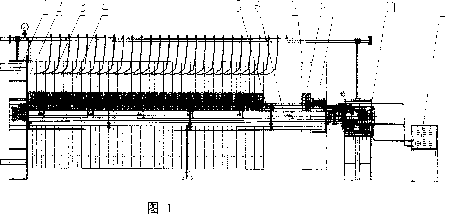
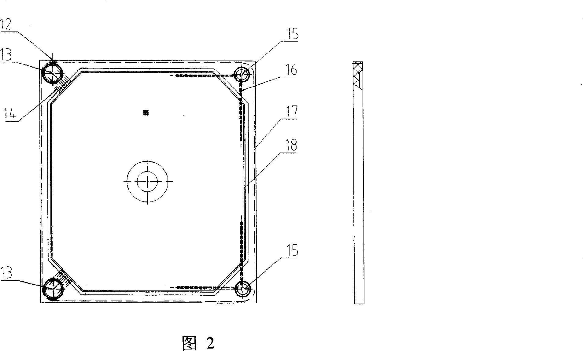
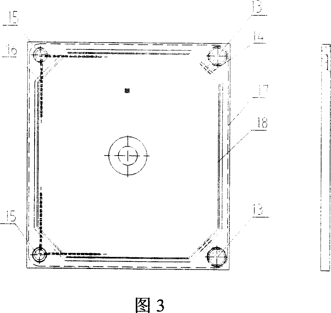
[0018]Embodiment 1: with reference to accompanying drawing 1~6. Fully automatic diaphragm wort filter press, which includes a frame part, a filter part, a pull plate part, a hydraulic part and an electrical control part. The frame part is mainly composed of a thrust plate 1, a compression plate 9, an oil cylinder seat 10 and a main beam 6 etc. parts are formed, and its manufacturing process is prior art, does not describe here. The filter part is composed of the filter plate 4, the diaphragm plate 3 and the filter cloth arranged on the main beam in a certain order. The filter plates and the diaphragm plates are arranged alternately to form several independent filter units—filter chambers. A sealing surface O-ring 17 is embedded around the filter plate 4 between the thrust plate 1 and the pressing plate 9, and the sealing surface contacts between the filter plate and the diaphragm plate. The automatic plate-drawing mechanism part is made up of hydraulic motor, manipulator 5, t...

Embodiment 2

[0020] Embodiment 2: On the basis of embodiment 1, the pressure filtration process of producing wort by mash mash in the beer production process, (1) close the wort filter press, and the hydraulic system automatically compresses the pressure plate and maintains it automatically At a certain pressure level, the filter press enters the state of automatic pressure maintenance; 1) The hydraulic system automatically compresses the pressure plate and maintains it within the pressure range of 15MPa-18MPa, and the entire filter press is in a closed state; (2) Hot water Quickly inject the mash into the filter press through the pump and pass through the feed hole to preheat the filter plate of the filter press to prevent the temperature from decreasing and the viscosity increasing when the mash enters the filter press. At the same time, the mash entering the filter press does not mix with Air contact to avoid oxygen absorption of wort; (3) The mash is quickly filled into the filter press...


PUM


Abstract

An automatic filter press of diaphragm malt extract and its process for saccharifying wort and filtering beer are disclosed. The process is carried out by shutting up malt filter press, retaining pressure automatically, charging stocks, filling wort into filter press by down-wort pump fast, pumping wort into from feed opening at one side of filter-pressing board bottom, filter pressing, filling filter press with wort, running malt extract out of liquid outlet at another side, flowing into boiler through balancing tank, inspecting non-material by mashing tub, shutting up down-wort pump automatically, filtering malt extract, blowing while extruding tank layer by diaphragm, press drying for tank layer, washing tank, pumping tank-washing water by down-wort pump, passing through tank layer and running out, reaching tank-washing water to a certain account, shutting up down-wort pump automatically, re-blowing while extruding tank layer from diaphragm, press drying for tank layer, opening exhaust valve of pipeline, discharging compression air in diaphragm board, opening filter board and dropping malt wort into bucket automatically.

Description

technical field [0001] The invention relates to a fully automatic diaphragm wort filter press for filtering beer wort, and a beer wort filtration process realized by the diaphragm wort filter press, which belongs to the field of filter equipment and beer wort filtration process manufacturing. Background technique [0002] The wort filtration methods used in beer production mainly include lauter tank method and filter press method. At present, the wort filtration of most breweries in my country adopts the lauter tank method. In the past ten years, people have made a series of improvements to the structure and working method of the filter tank, but this filter method always has the disadvantages of long filter time, low yield and low degree of automation. Although various auxiliary measures have been taken, these problems have not been fundamentally resolved. With the development of breweries in the direction of large-scale, the capacity of saccharification equipment will al...

Claims


Application Information

Patent Timeline
IPC IPC(8): C12C7/165B01D25/12
Inventor 张景徐孝雅倪国炳张正洪陈科庆徐美良张鹏环明祥
Owner HANGZHOU XINGYUAN FILTER TECH
Learn More