

Low-voltage linear adjuster
A voltage regulator, linear voltage technology used in LDOs. It can solve the problems of increasing the complexity of the chip, increasing the cost, increasing the chip area, etc., to achieve the effect of improving the transient response and voltage regulation ability, increasing the power consumption, and increasing the chip area.
- Summary
- Abstract
- Description
- Claims
- Application Information
AI Technical Summary
Problems solved by technology
Method used
Image

Examples
Embodiment Construction
[0053] Below according to accompanying drawing and embodiment the present invention will be described in further detail:
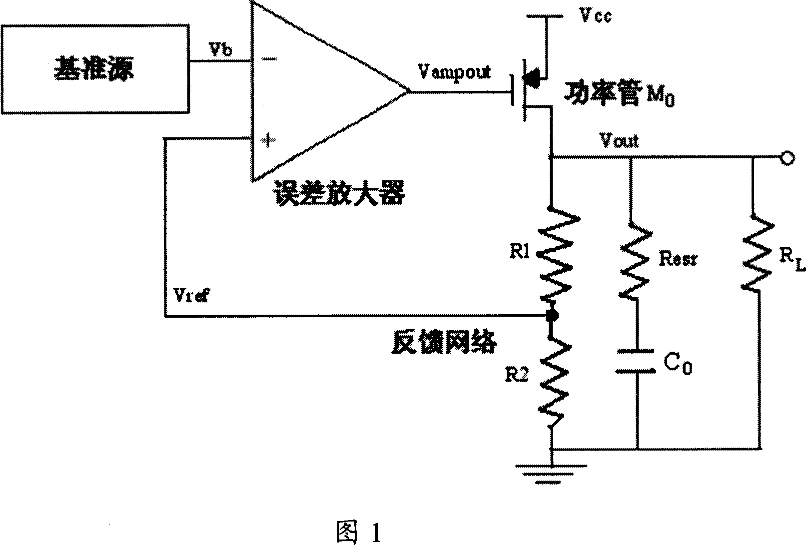
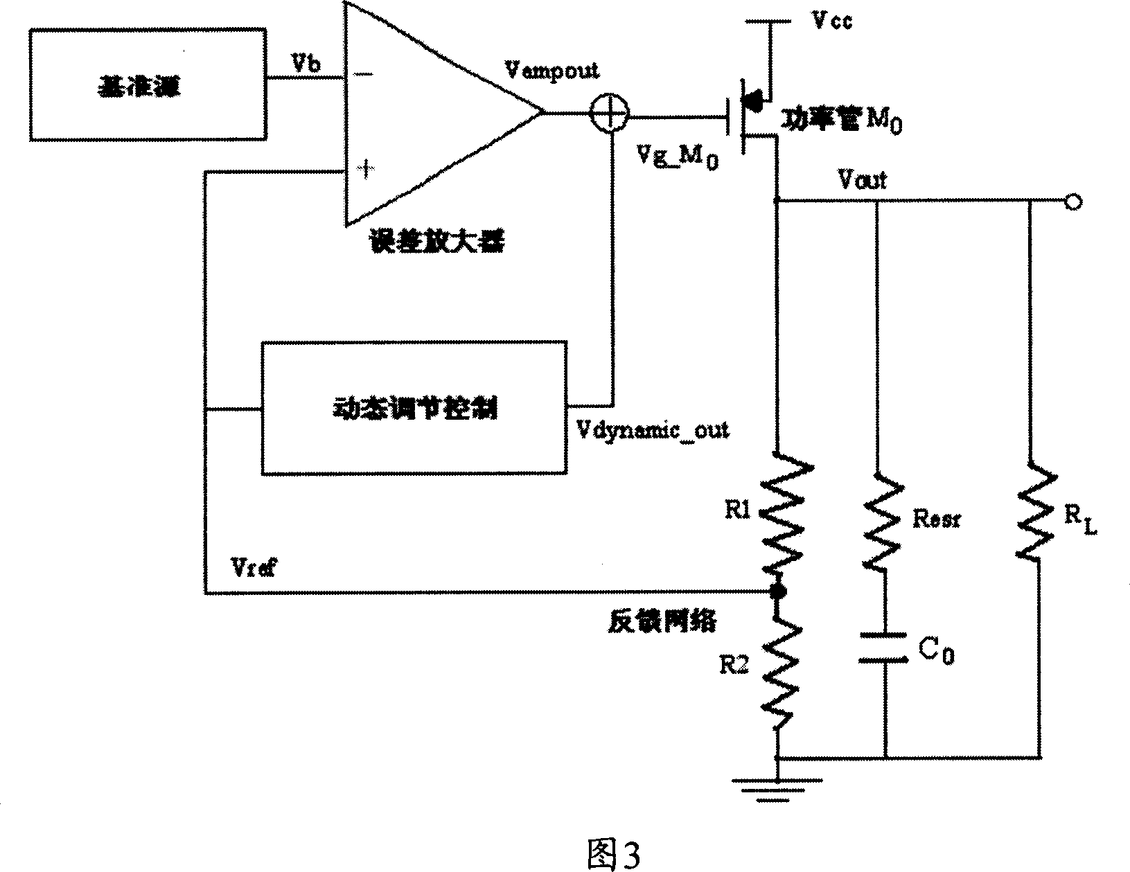
[0054] The invention realizes improving the transient response and voltage regulation ability of the LDO while hardly increasing the chip area and power consumption. It can be seen from the analysis of the working principle of the LDO core circuit introduced in the technical background that the LDO essentially uses a feedback loop to control the gate-source-drain voltage of the power transistor to achieve a stable output of the system voltage. Therefore, increasing the bandwidth can improve the transient response of the LDO, but the increase in the bandwidth will put forward higher requirements for the circuit design. On the premise that the bandwidth is determined, we propose a scheme to improve the LDO transient response and voltage regulation ability by dynamically adjusting the gate-source voltage of the power transistor. The core circuit of the prese...
PUM
 Abstract
Description
Claims
Application Information