Railroad clearance high speed dynamic detecting device

A dynamic detection, high-speed technology, applied in measurement devices, navigation through speed/acceleration measurement, mapping and navigation, etc., can solve the problems of slow speed, few measurement points, no railway boundary high-speed dynamic detection device, etc., to achieve high additional Benefit, improve work efficiency, significant practical value and the effect of economic benefits

Inactive Publication Date: 2007-12-05
LEADOR SPATIAL INFORMATION TECH CORP
View PDF0 Cites 29 Cited by
  • Summary
  • Abstract
  • Description
  • Claims
  • Application Information

AI Technical Summary

Problems solved by technology

At present, the detection of the railway boundary mainly relies on manual observation. If there is an object close to the boundary, it is measured with a plumb line and a tape measure. Not only is the speed s

Method used


Image

  • Railroad clearance high speed dynamic detecting device
  • Railroad clearance high speed dynamic detecting device

Examples


Embodiment Construction

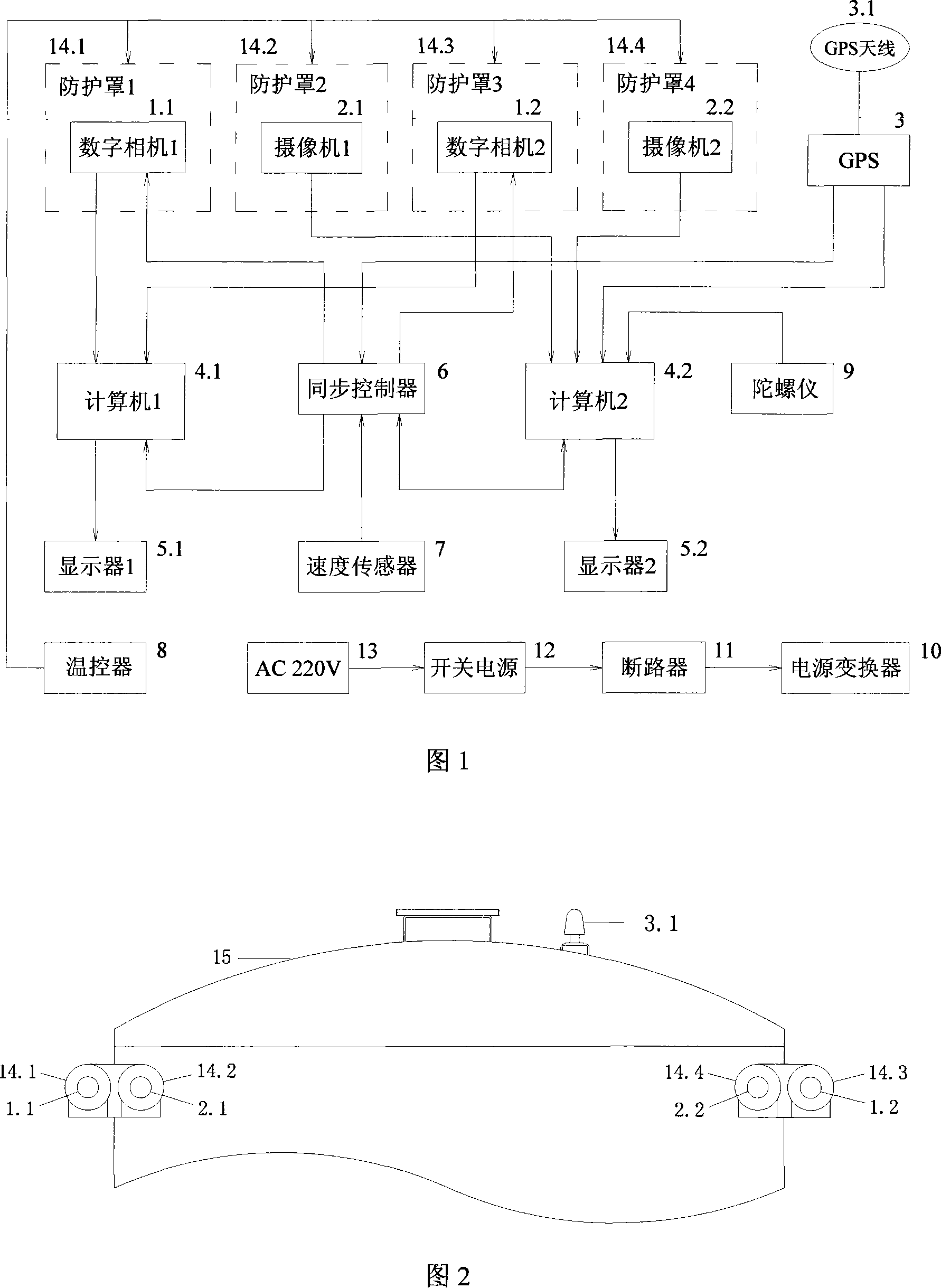
[0040] Further illustrate below in conjunction with accompanying drawing and embodiment:

[0041] 1. Overall

[0042] 1. As mentioned above, as shown in Figure 2, the 1st, 2nd digital camera (1.1, 1.2) and the 1st, 2nd video camera (2.1, 2.2) are respectively installed in the both sides of the test carriage (15) front end top. Because the test car can not turn around when traveling on the railway, the same position at the other end of the test car (15) should also be equipped with the same 1st, 2nd digital camera (1.1, 1.2) and the 1st, 2nd video camera (2.1, 2.2 ). Turn on the equipment at one end according to the direction of train travel or operation requirements. The first and second digital cameras (1.1, 1.2) are used for image acquisition on both sides of the train; the first and second cameras (2.1, 2.2) are used for landscape video acquisition on both sides of the train.

[0043] 2. The GPS antenna (3.1) is installed on the top of the test compartment (15). The firs...


PUM


Abstract

This invention discloses a sort of high speed dynamic checking device of the railroad delimitation, it relates to a sort of railroad delimitation checking device. This invention uses synthetically several high-new technique in that the GPS global positioning system, the body measurement system, the dead rocking system, the auto-control, and so on. It realizes the measure and collection of the space geographical data and the attribute data to the objects which is in or near the railroad. It notes the actual photograph along the railroad real time. It provides the measurement result of the delimitation scene by the measurement function of the post treatment. This invention can shoot clear sight kinescope along the railroad too, it choices one point in the wheel path map, it can obtain expediently and fleetly the sight kinescope of this point and progress play. It helps to obtain the status message of the railroad establishment, and it progresses the conduction to the railroad capital. This invention is the same with this checking area of internal railroad delimitation, and has remarkable use value and economic returns.

Description

technical field [0001] The invention relates to a railway boundary detection device, in particular to a railway boundary high-speed dynamic detection device. Specifically, the present invention is an integrated application of various cutting-edge technological means such as satellite positioning, dead reckoning and mobile close-range photogrammetry, which is installed on the electric service test carriage and dynamically detects railway information during high-speed driving. system. The invention can collect the spatial position and image data of the surrounding facilities of the railway in real time and efficiently, measure the railway boundary, and provide decision-making basis for the management of railway assets, guiding maintenance and repair operations, and ensuring the safe operation of the railway. Background technique [0002] The buildings and facilities around the railway need to be inspected regularly or when necessary to determine whether they exceed the limit ...

Claims


Application Information

Patent Timeline
IPC IPC(8): G01C11/00G01C11/04G01C21/00G01C21/18G01S1/02G01S5/02G01S19/42H04N7/18
Inventor 罗才安
Owner LEADOR SPATIAL INFORMATION TECH CORP
Why Eureka
Try Eureka