Filling method for isolation groove

A filling method and technology for isolating trenches, which are applied in the field of filling shallow trench isolation trenches, can solve the problems of large surface roughness of STI isolation structure trenches, and achieve the effect of reducing the surface roughness of the wafer and improving the flatness.

Inactive Publication Date: 2007-12-19
SEMICON MFG INT (SHANGHAI) CORP +1
View PDF1 Cites 2 Cited by
  • Summary
  • Abstract
  • Description
  • Claims
  • Application Information

AI Technical Summary

Problems solved by technology

[0004] In view of this, the purpose of the present invention is to provide a method for filling isolation trenches, to solve the problem of relatively large surface roughness after trench filling of STI isolation structures

Method used


Image

  • Filling method for isolation groove
  • Filling method for isolation groove
  • Filling method for isolation groove

Examples


Embodiment Construction

[0037] In order to make the above objects, features and advantages of the present invention more comprehensible, specific implementations of the present invention will be described in detail below in conjunction with the accompanying drawings.

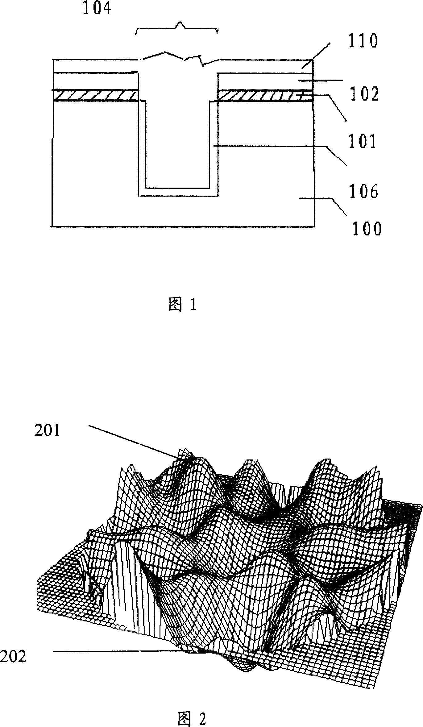
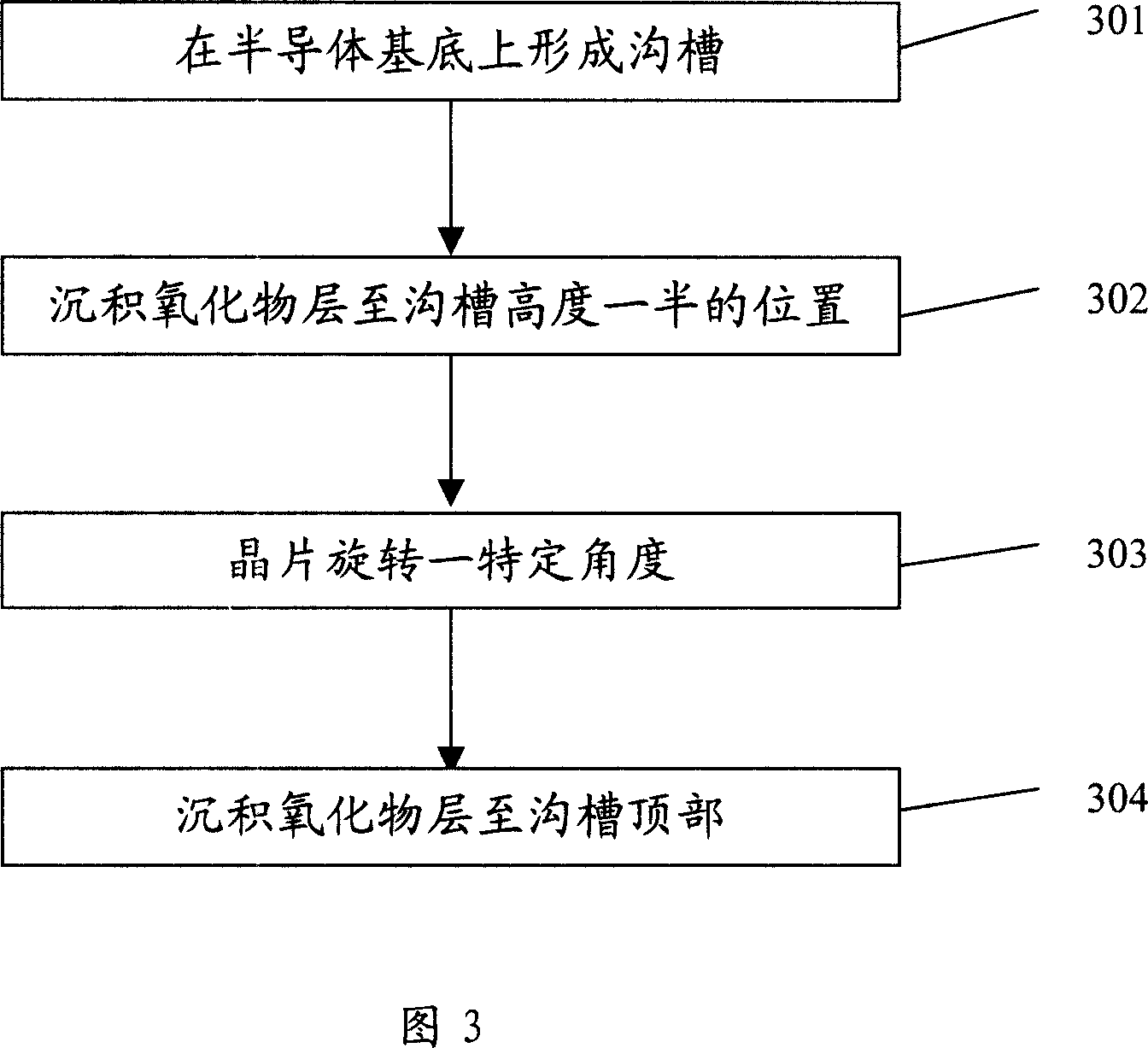
[0038] FIG. 3 is a flowchart of a method for manufacturing a semiconductor device of the present invention. First, a trench is formed on a semiconductor substrate (S301); then, an oxide layer is deposited to a position halfway to the height of the trench (S302); then, the wafer is rotated by a certain angle (S303); finally, an oxide layer is deposited to Groove top (S304). The above method is only a brief description of the technical solution of the present invention, and the method of the present invention will be described in detail below in the description.

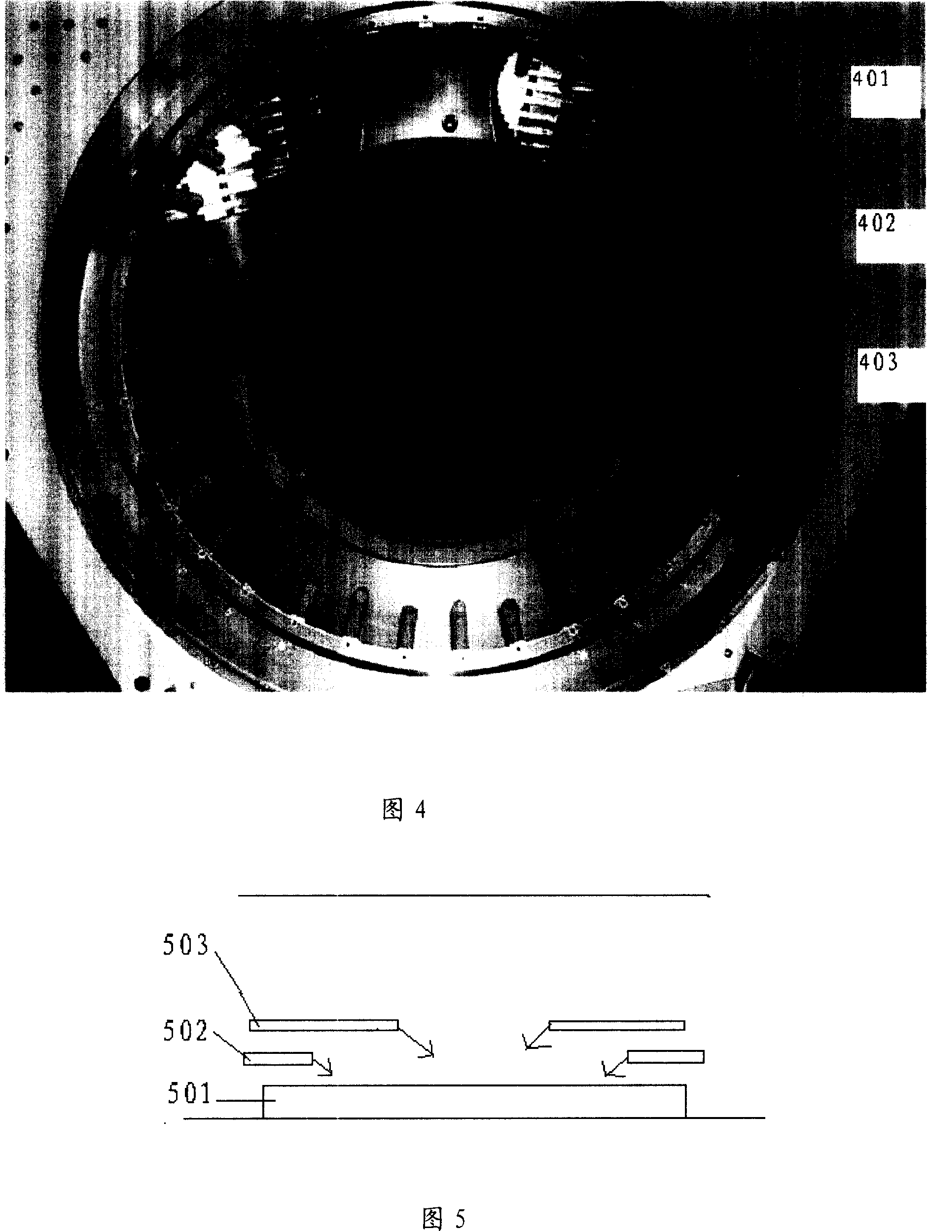
[0039] Fig. 4 is a structural diagram of an HDP reaction chamber (chamber). As shown in FIG. 4 , this figure is a position structure diagram of a wafer in a deposition chambe...


PUM


Abstract

This invention discloses a filling method for isolating grooves including: a, forming a groove on a semiconductor base, b, depositing an oxide layer to the groove half of the height of the groove, c, rotating the wafer to a specific angle, d, depositing an oxide layer to the top of the groove, which can solve the problem that the surface roughness of the STI structure is large after solving the technical process of STI HDP and is ready for the CMP of next step.

Description

technical field [0001] The invention relates to the technical field of semiconductor manufacturing, in particular to a method for filling (Gap-filling) isolation trenches of shallow trenches (shallow trench isolation STI). Background technique [0002] With the rapid development of semiconductor technology, the feature size of semiconductor devices has been significantly reduced, and accordingly higher requirements have been placed on chip manufacturing processes. With the further high density, miniaturization and high speed of IC devices, especially with the With the development of semiconductor feature size to 65 nanometers or even finer structures, the tolerance range of the process is correspondingly reduced, and higher requirements are put forward for the filling of insulating dielectrics, especially for shallow trench isolation (shallow trench isolation, STI). [0003] The patent with the publication number of CN1531057A discloses a method for filling an STI trench, wh...

Claims


Application Information

Patent Timeline
Patent Type & Authority Applications(China)
IPC IPC(8): H01L21/762H01L21/316
Inventor 游宽结杨海涛平延磊
Owner SEMICON MFG INT (SHANGHAI) CORP
Why Eureka
Try Eureka