Spherical multi-freedom altrasonic electric machine of single vibrator longtitude bend sandwich changer type

An ultrasonic motor and transducer technology, which is applied in the directions of generators/motors, piezoelectric effect/electrostrictive or magnetostrictive motors, electrical components, etc. , small driving torque, etc., to achieve the effect of three-dimensional proportional coordination of configuration, simple structure and large output torque

Inactive Publication Date: 2007-12-19
HARBIN INST OF TECH
View PDF0 Cites 30 Cited by
  • Summary
  • Abstract
  • Description
  • Claims
  • Application Information

AI Technical Summary

Problems solved by technology

[0004] The purpose of the present invention is to provide a single vibrator longitudinal bending sandwich transducer-type spherical multi-degree-of-freedom ultrasonic motor, which can solve the three-dimensional unbalanced configuration,

Method used


Image

  • Spherical multi-freedom altrasonic electric machine of single vibrator longtitude bend sandwich changer type
  • Spherical multi-freedom altrasonic electric machine of single vibrator longtitude bend sandwich changer type
  • Spherical multi-freedom altrasonic electric machine of single vibrator longtitude bend sandwich changer type

Examples


specific Embodiment approach 1

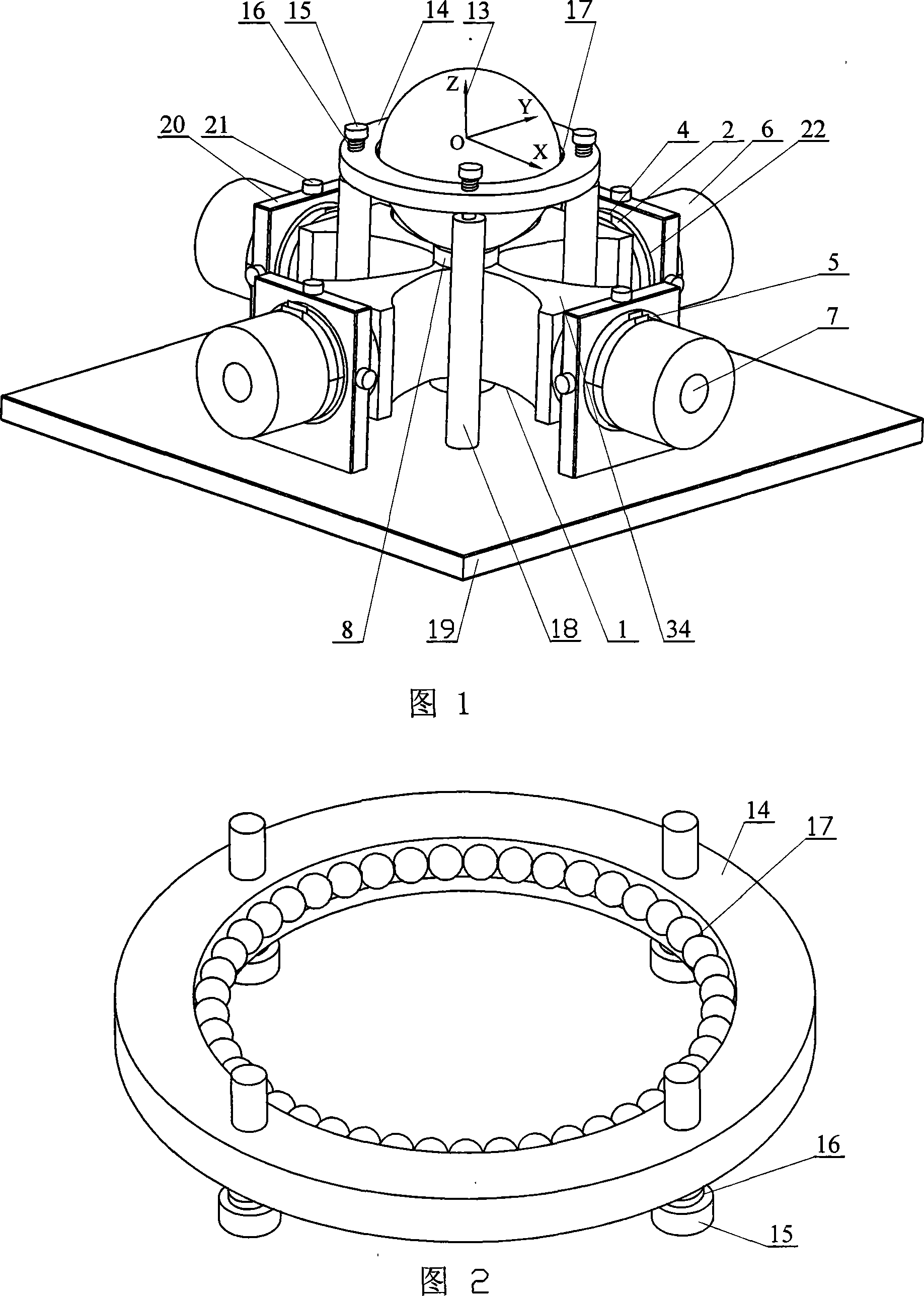
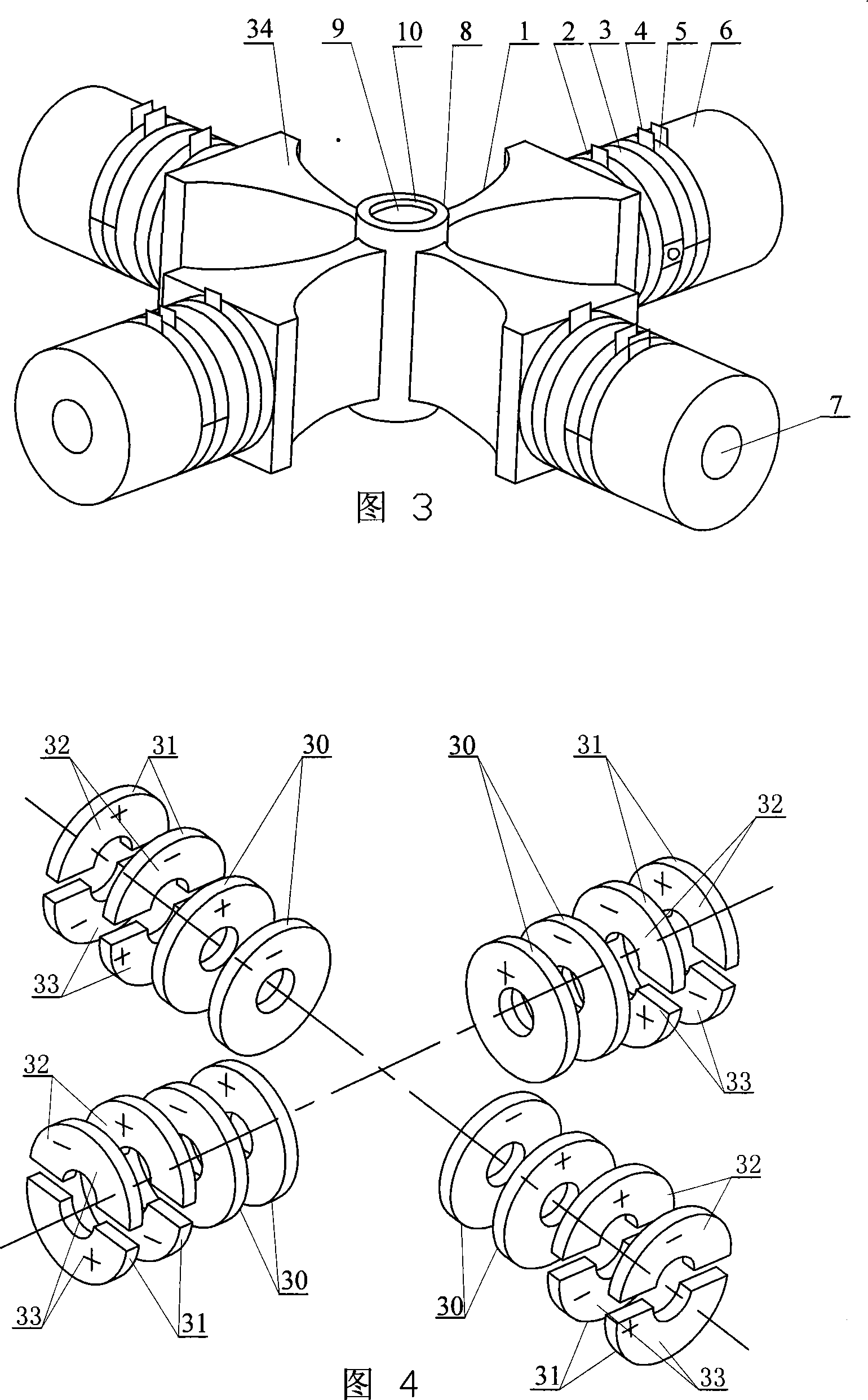
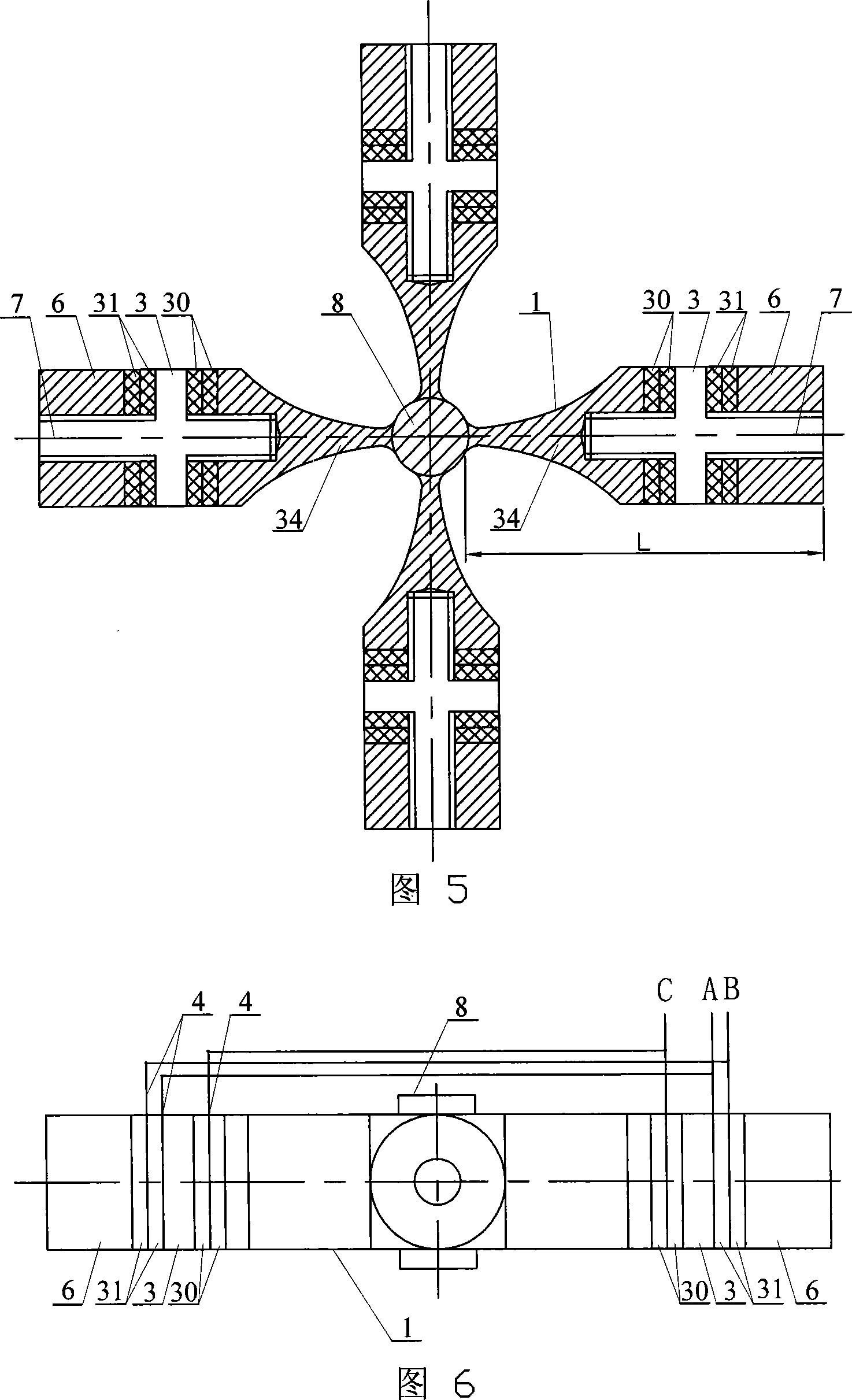
[0008] Embodiment 1: This embodiment is described with reference to FIGS. 1 to 7 . This embodiment is composed of a single-vibrator longitudinal-bending sandwich transducer, a fixed component and a mover ball 13; the single-vibrator longitudinal-bending sandwich transducer consists of a cross Orthogonal horn 1, longitudinal vibration piezoelectric ceramic sheet group 2, flange 3, electrode copper sheet 4, bending vibration piezoelectric ceramic sheet group 5, end cap 6, stud 7 and driving foot 8; A stud 7 is respectively provided on the vertical axis of the orthogonal horn 1, the stud 7 is provided with a flange 3, and the flange 3 is located at the nodal surface position of the longitudinal vibration of the single vibrator longitudinal bending sandwich transducer. The stud 7 between the flange 3 and the large end face of the cross orthogonal horn 1 is equipped with a longitudinal vibration piezoelectric ceramic plate group 2, and the stud 7 between the flange 3 and the end cov...

specific Embodiment approach 2

[0009] Embodiment 2: This embodiment is described with reference to FIGS. 1 to 3 and 5. The fixing assembly of this embodiment consists of a top bead holder 14, a preload 15, a preload spring 16, a sliding ball 17, a preload bracket 18, The base 19 and the driver fixing frame 20 are composed; the ring groove of the top bead frame 14 is equipped with sliding balls 17 , the top bead frame 14 is mounted on the mover ball 13 , and the top bead frame 14 passes through the pre-tightening member 15 and the pre-tightening member. The spring 16 is connected to the upper end of the preloading bracket 18, the lower end of the preloading bracket 18 is fixed on the base 19, the driver fixing frame 20 is fixed on the base 19, the driver fixing frame 20 is fixedly connected with the flange 3, the The single-vibrator longitudinal-bending sandwich transducer is mounted on the base 19 . In this way, the top ball frame 14 is used to assemble the sliding balls 17 to limit the position of the move...

specific Embodiment approach 3

[0010] Embodiment 3: This embodiment is described with reference to FIG. 1 and FIG. 3 . The difference between this embodiment and Embodiment 2 is that an elastic rubber ring 22 is added to the fixing assembly of this embodiment; the elastic rubber ring 22 is provided with between the drive holder 20 and the flange 3 . This arrangement can reduce the influence on the natural mode shape of the single-element longitudinal-bending sandwich transducer.


PUM


Abstract

This invention relates to a supersonic motor, in which, a flange is set on a screw post, compressional vibration piezoelectric ceramic plate sets, bent vibration piezoelectric ceramic plate sets, pole copper plates and a cover are mounted on the post and fixed to become one unit with a cross orthogonal luff rod by the post, the polarization directions of two adjacent bent vibration piezoelectric ceramic sets are opposite and those of the two adjacent compressional piezoelectric ceramic sets are opposite, a drive foot is placed at the center of the luff rod and fixed on it and a rotor ball sits on the drive foot and the fixed component fastened to the flange.

Description

technical field [0001] The invention relates to an ultrasonic motor, which belongs to the technical field of piezoelectric ultrasonic motors. Background technique [0002] Piezoelectric ultrasonic motors have been widely used in optoelectronics, aerospace, biological and genetic engineering, robots and household appliances due to their simple and flexible structure, various motion forms, small size, light weight, fast response speed, and no electromagnetic interference. and other technical fields. At present, most ultrasonic motors in practical applications can only perform linear motion or rotation with one degree of freedom. In the fields of spherical joints for omnidirectional bionic motion, flexible joints of high-performance robots, and robot eyeballs, motors with multiple degrees of freedom are required to move drive. At present, the spherical multi-degree-of-freedom ultrasonic motors developed at home and abroad mostly adopt the multi-vibrator drive form, that is, i...

Claims


Application Information

Patent Timeline
IPC IPC(8): H02N2/12
Inventor 陈维山赵学涛刘军考谢涛
Owner HARBIN INST OF TECH
Why Eureka
Try Eureka