Gas supply-discharge system for base plate sintering furnace

A technology of exhaust system and sintering furnace, which is applied to furnaces, furnace types, electrical components, etc., can solve problems such as increased operating costs, blockage of heat exchangers, low energy conversion efficiency, etc., to improve energy conversion efficiency and improve decomposition efficiency. Effect

Inactive Publication Date: 2007-12-26
KOYO THERMO SYST CO LTD
View PDF1 Cites 8 Cited by
  • Summary
  • Abstract
  • Description
  • Claims
  • Application Information

AI Technical Summary

Problems solved by technology

[0007] However, even if the gas discharged from the sintering furnace is catalytically treated, the organic matter on the glass substrate cannot be sufficiently removed. As a result, the heat exchanger is clogged with deposits in a short period of time, and continuous operation cannot be continued for a long time. Therefore, The operating efficiency of the device is very low, which is very uneconomical
[0008] Therefore, in fact, although the gas discharged from the sintering furnace is mostly treated by waste gas treatment equipment, in this case, in addition to meeting the above-mentioned low energy conversion efficiency, it is also necessary to treat the waste liquid after treatment. , so there is a problem of increased operating costs

Method used


Image

  • Gas supply-discharge system for base plate sintering furnace
  • Gas supply-discharge system for base plate sintering furnace
  • Gas supply-discharge system for base plate sintering furnace

Examples


Embodiment Construction

[0046] Hereinafter, embodiments of the present invention will be described in detail with reference to the drawings.

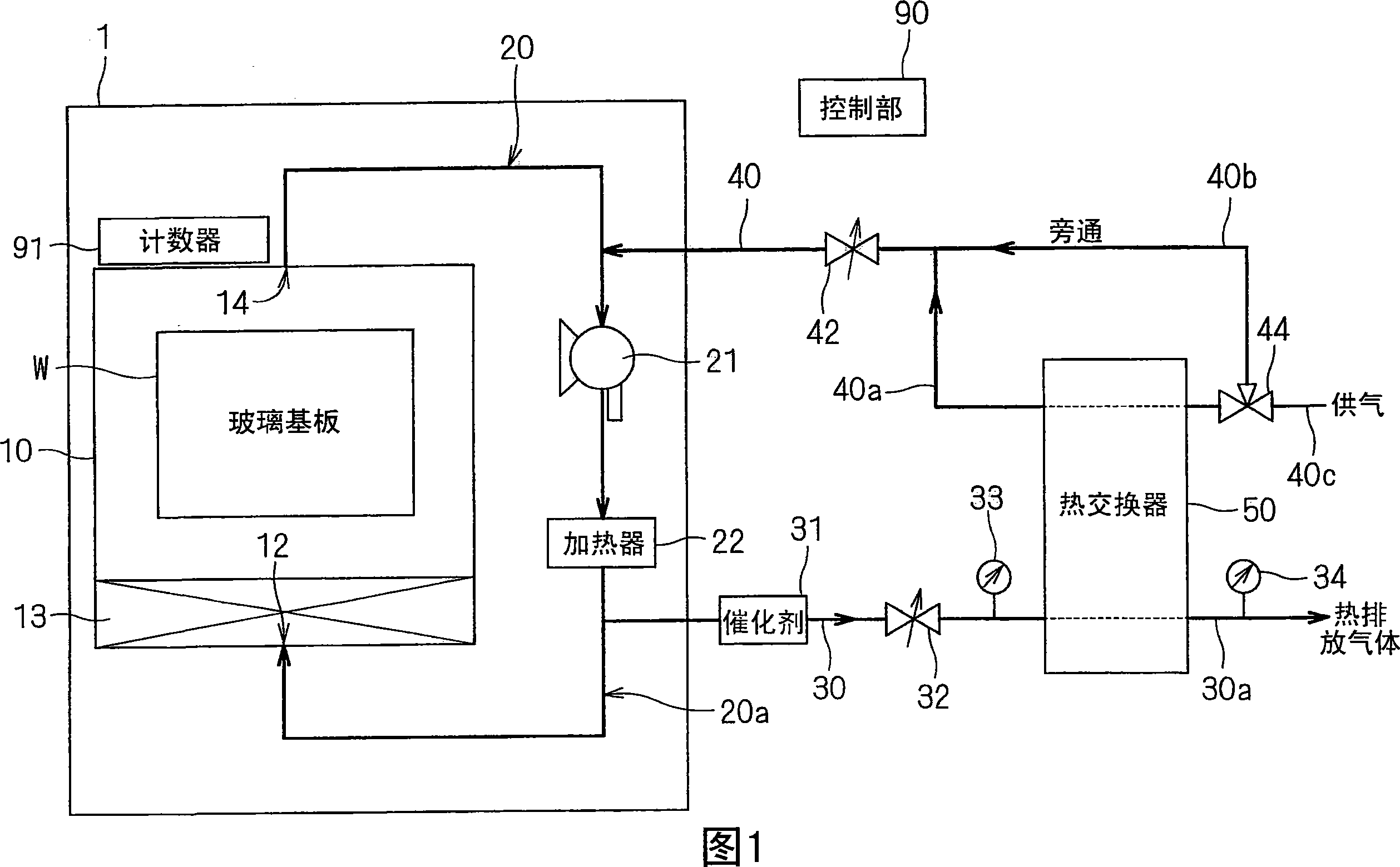
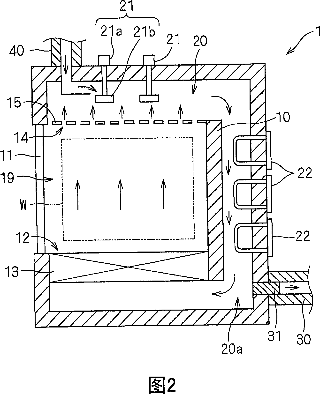
[0047] FIG. 1 is a schematic diagram showing the configuration of main parts of an air supply and exhaust system of a substrate sintering furnace according to the present invention. In addition, FIG. 2 is a cross-sectional view of the substrate sintering furnace seen from above. The substrate sintering furnace 1 is a hot air furnace for sintering a square glass substrate W (substrate in the present invention) coated with colored ink or the like. The substrate sintering furnace 1 has: a furnace body 10 for accommodating a glass substrate W and performing a sintering process; a circulation path 20 for circulating hot air discharged from the furnace body 10 and supplying it again to the furnace body 10; a fan 21 provided in The circulation path 20 is used to circulate the hot air; and the heater 22 is arranged on the circulation path 20 for heating the hot air. ...


PUM


Abstract

The invention provides an air intake and exhaust system for the substrate baking furnace which has a high energy conversion efficiency and a long time reliable operation. The heat discharge gas discharged from the vent of the furnace passes through fans and is fed to the circulation path as a hot-air flow. Then the flow is heated by a heater and purified by a heat resistant HEPA filter and fed to the inner space of the furnace again from a spraying port. In the circulation process, a part of the heat wind heated by the heater flows into the vent-pipe and passes through the catalyst unit. The discharge gas flows into a heat exchanger after most organic matters in the discharge gas are decomposed, because the high temperature discharge gas heated again passes through the catalyst unit. The heated feeding gas whose temperature is boosted by a heat exchange in the heat exchanger with the discharge gas are fed to the circulation path.

Description

technical field [0001] The present invention relates to an air supply and exhaust system in a substrate sintering furnace for controlling glass substrates for liquid crystal display devices, glass substrates for PDP (plasma display panels), or substrates for thin-plate electronic components such as semiconductor wafers ( Hereinafter simply referred to as "substrate") is subjected to sintering treatment. Background technique [0002] One of the manufacturing steps of the color filter includes a step of sintering the glass substrate on which the color ink is sprayed by inkjet. This sintering step is carried out by maintaining the substrate in an air atmosphere for a predetermined time in a sintering furnace whose temperature has been raised to a predetermined sintering temperature. In addition, in the case of forming metal wiring on a glass substrate, the glass substrate is sintered in an inert gas atmosphere such as nitrogen in the same sintering furnace. Regardless of the ...

Claims


Application Information

Patent Timeline
Patent Type & Authority Applications(China)
IPC IPC(8): F27D7/00F27D7/04F27B17/00H01L21/00
CPCH01L21/67017H01L21/67109
Inventor 村冈佑介宫路恭祥长岛靖
Owner KOYO THERMO SYST CO LTD
Why Eureka
Try Eureka