High speed full-automatic paster machine array type mounting head

A placement head and array-type technology, which is applied in the direction of assembling printed circuits, electrical components, electrical components, etc., can solve the problems of restricting technology popularization, and achieve the effect of compact and simple structure, low quality and low design cost

Inactive Publication Date: 2008-01-02
BEIHANG UNIV
View PDF0 Cites 31 Cited by
  • Summary
  • Abstract
  • Description
  • Claims
  • Application Information

AI Technical Summary

Problems solved by technology

Due to the shortcomings of the above-mentioned several types of placement head systems, their development and the popularization of related technologies are limited to a certain extent.

Method used


Image

  • High speed full-automatic paster machine array type mounting head
  • High speed full-automatic paster machine array type mounting head
  • High speed full-automatic paster machine array type mounting head

Examples


Embodiment Construction

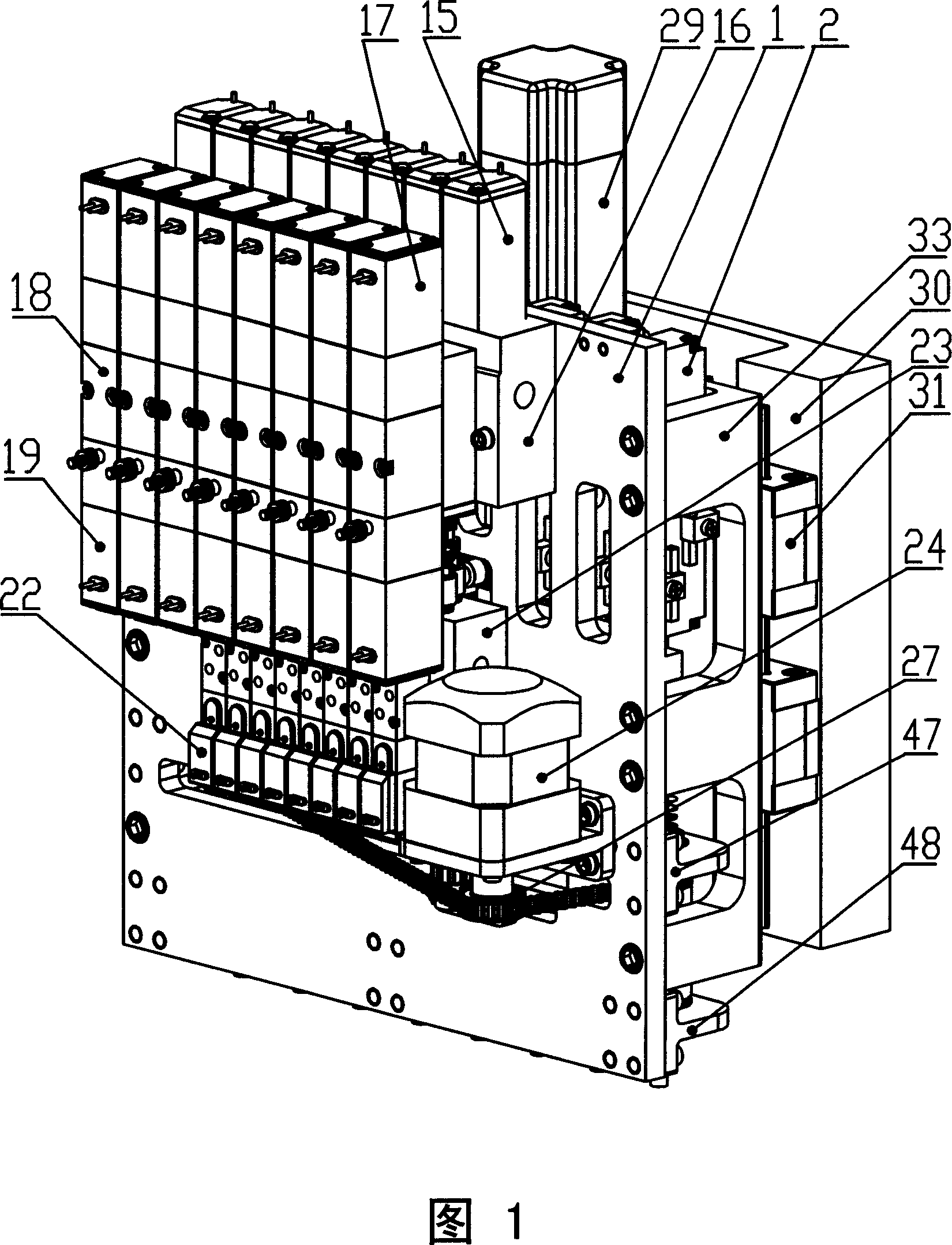
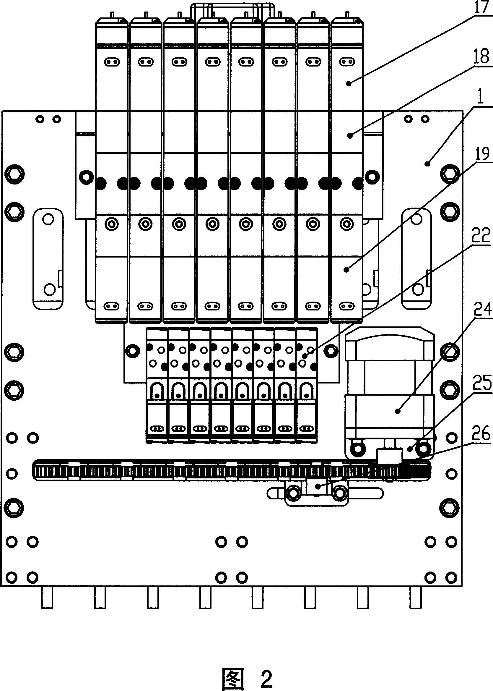
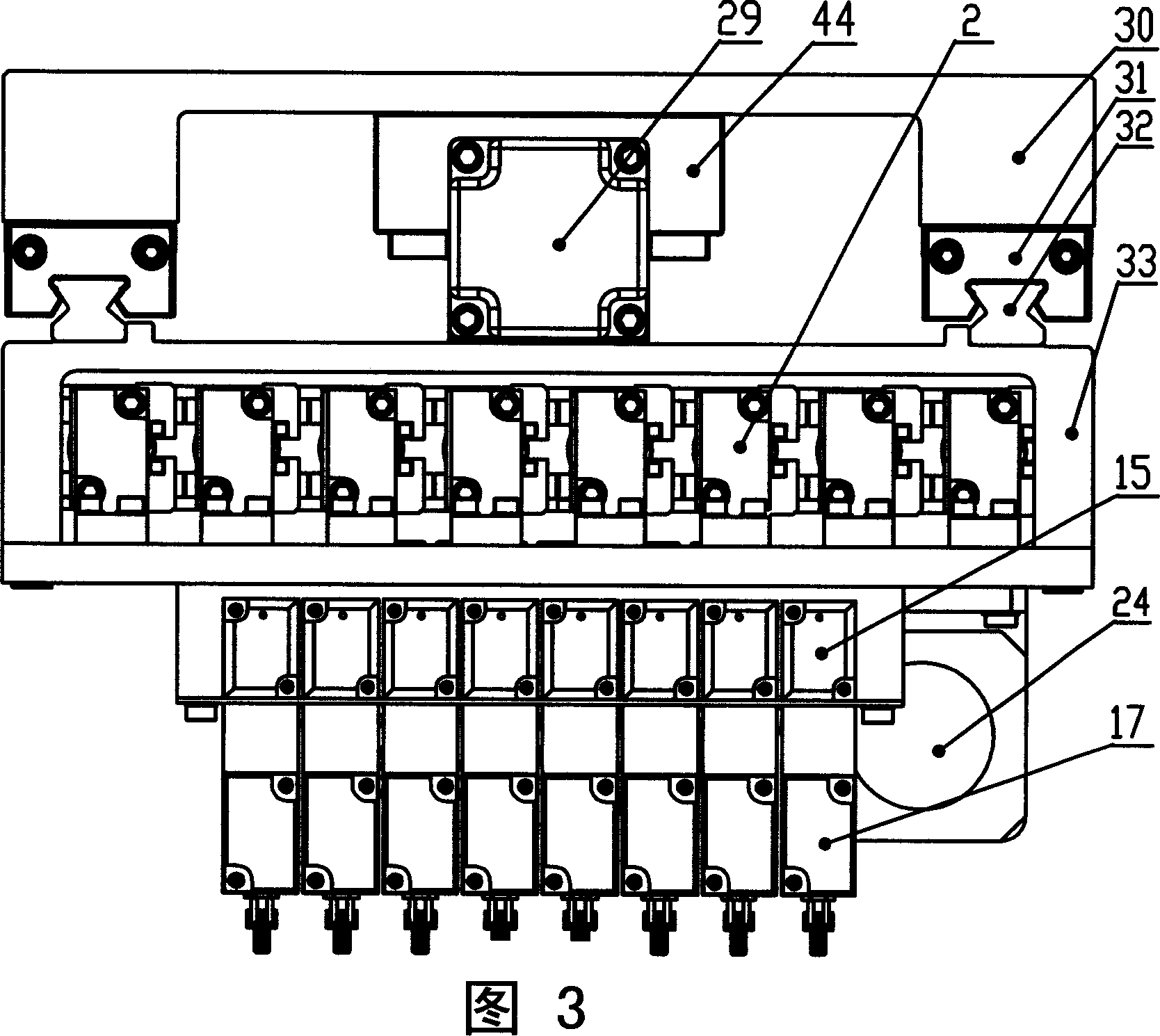
[0051] The placement head includes a main frame 1, a cylinder module, a ball spline module, a cylinder control module, a vacuum system, a θ angle control system, and an overall Z-axis motion system, and is characterized by:

[0052] As shown in Figures 1 and 2, the main frame 1 is a large plane with corresponding mounting threaded holes, an air channel on the upper part, and a synchronous toothed belt channel on the lower part;

[0053] As shown in Figure 6, the cylinder module is a group of miniature precision square actuator cylinders 2 with magnetic switches 4, the structure of the square actuator cylinder 2 is shown in Figure 8, the piston rod is hollow, and there are 3 interfaces, A, B It is the air port for piston movement, C is the vacuum air supply port, the square executive cylinder 2 is uniformly and closely divided above the main frame 1, and an electromagnetic shielding plate 3 is added between adjacent cylinders. The piston rod of the square executive cylinder 2 is...


PUM


Abstract

The invention provides a high-speed full-automatic paste machine array paste head, which uses a main frame as core, while other systems and modules are assembly on the main frame. A cylinder module, a cylinder control module, and a Z-axis motion system form the Z-axis motion of the paste head. When in use, the cylinders of the cylinder module execute paste missions in turn, while only one cylinder works at one time. A ball spline module and a theta control system process the bias correction of chop. When moves at theta angle, all splines of the ball spline module work together, while the bias parameter of each spline is realized by a control-software. A vacuum system generates the control signals for the blow and adsorption of a vacuum resource and a chip, while the vacuum resource via a vacuum inlet of a micro cylinder in the cylinder module, a hollow piston rod, and a hollow spline shaft of the ball spline module, transmits vacuum to the end of the paste head to absorb and paste the chip.

Description

(1) Technical field [0001] The invention relates to the field of SMT (Surface Mount Technology, surface mount technology) placement machines, in particular to the technical field of an electronic surface mount placement machine and its mounting head assembly. (2) Background technology [0002] Surface mount technology (SMT) originated in the late 1950s, with the invention of semiconductor integrated circuits, thick and thin film hybrid integrated circuits. Due to the hard texture of the ceramic substrate, it is not convenient to punch holes for component insertion, and chip components are used, so chip capacitors and chip resistors appear, and active components use bare chips, wire bonding or flip chips, etc. form to assemble. After entering the 1970s, the application of hybrid integrated circuits began to expand from the military field to the industrial and civilian fields, and the production scale expanded rapidly. At the end of the 1970s and the beginning of the 1980s, ...

Claims


Application Information

Patent Timeline
Patent Type & Authority Applications(China)
IPC IPC(8): H05K13/04H05K3/32
Inventor 刘强吴文镜郑妍袁松梅
Owner BEIHANG UNIV
Why Eureka
Try Eureka