
Bearing of motor driven fuel pump

A fuel pump and motor-type technology, applied in the field of motor-type fuel pump bearings, can solve the problems of accelerated wear process and lack of wear resistance, and achieve good corrosion resistance

Active Publication Date: 2008-01-02
DIAMET CORP +1
View PDF4 Cites 15 Cited by
  • Summary
  • Abstract
  • Description
  • Claims
  • Application Information

AI Technical Summary

Problems solved by technology

However, conventional Cu-based sintered alloy bearings have high strength, but they do not have sufficient wear resistance, so the current situation is that the wear process of the bearing is accelerated, and the service life is reached in a short period of time.

Method used


Image

  • Bearing of motor driven fuel pump
  • Bearing of motor driven fuel pump

Examples


Embodiment Construction

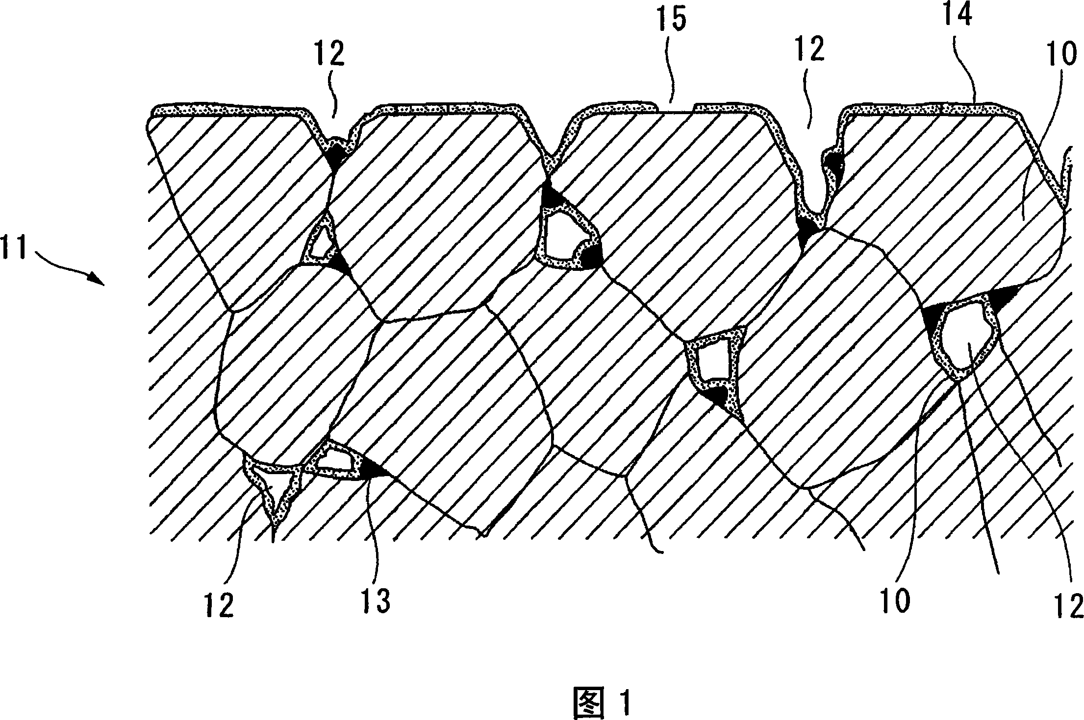
[0024] Next, the bearing of the present invention will be described with reference to FIG. 1 . FIG. 1 is a schematic diagram of a cross-sectional structure observed when a surface cut at a surface passing through the central axis of the bearing is observed with an optical microscope on the surface portion of the bearing. In this bearing, open pores 12 having a porosity of 8 to 18% are distributed in a bearing matrix 11 made of Cu—Ni alloy grains 10 . In addition, the P component is distributed in the grain boundaries of the Cu—Ni alloy particles 10 , and the free graphite 13 is distributed along the inner surfaces of the open pores 12 . If such a Cu—Ni based sintered alloy is used to constitute a bearing, good wear resistance can be ensured by the Cu—Ni alloy grains 10 constituting the base 11 . In addition, based on the effect of the highly lubricating free graphite 13 free on the inner surface of the air hole 12 and the fluid lubrication film formed by the liquid fuel suppl...


PUM

PropertyMeasurementUnit
porosityaaaaaaaaaa
particle diameteraaaaaaaaaa

Abstract

A bearing of a motor driven fuel pump which comprises a Cu-Ni based sintered alloy having a chemical composition that Ni: 21 to 35 %, Sn: 5 to 12 %, C: 3 to 7 %, P: 0.1 to 0.8 % and the balance: Cu and inevitable impurities, wherein pores are formed in the matrix thereof with a porosity of 8 to 18 %, wherein the p component is mainly contained in the grain boundary portion, wherein free graphite is distributed along the inner surface of open pores which open to the surface of the bearing and extend into the inside of the bearing, and wherein an Sn high concentration alloy layer having an Sn content of 50 mass % or higher is formed in the inner surface of the above open pores and around openings of the above open pores.

Description

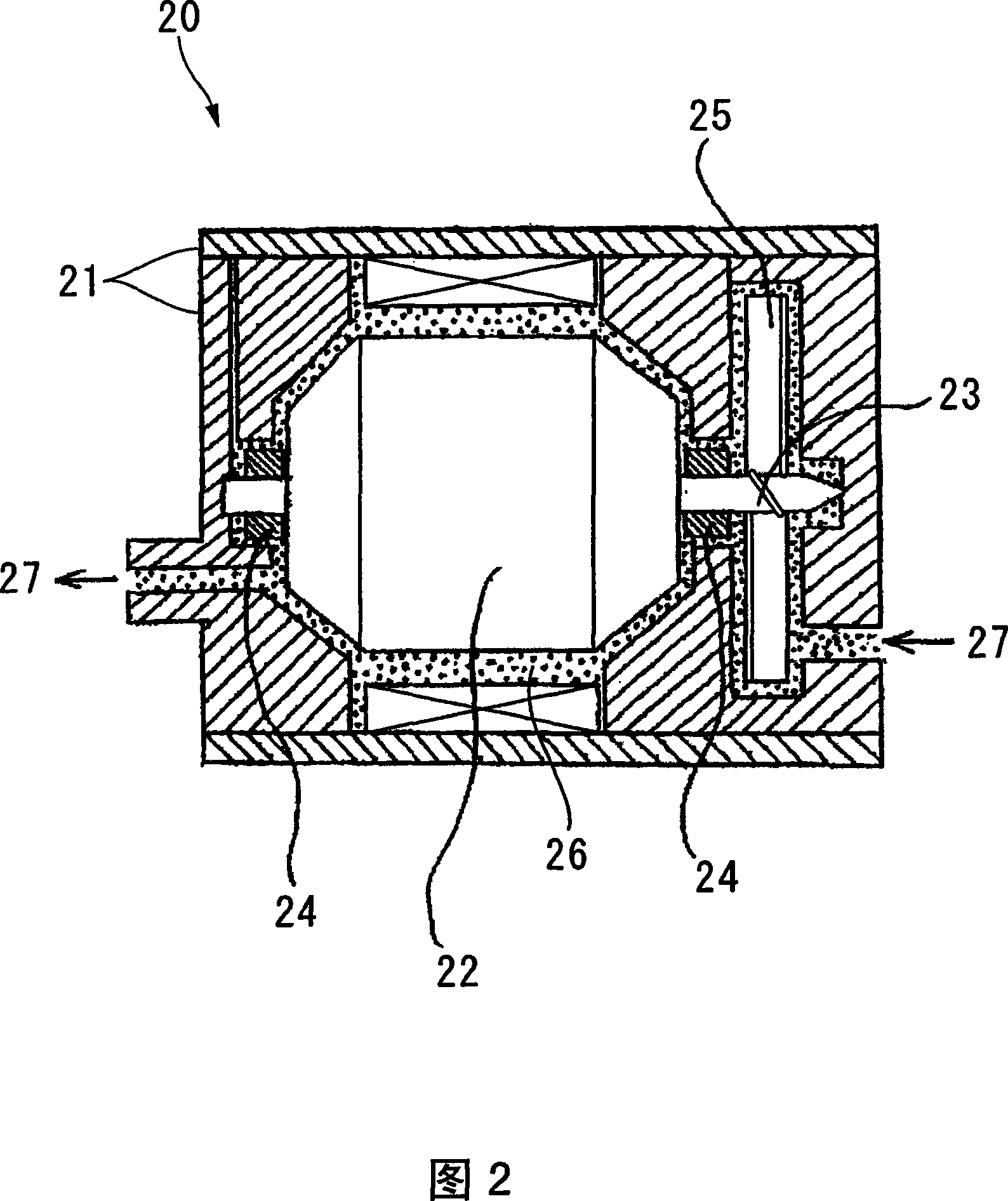
technical field [0001] The present invention relates to a bearing of a motor fuel pump made of Cu-Ni based sintered alloy. [0002] this application claims priority based on Japanese Patent Application No. 2005-009989 for which it applied on January 18, 2005, and uses the content here. Background technique [0003] Conventionally, engines using liquid fuels such as gasoline and light oil generally have motor-type fuel pumps. For example, a motor-type fuel pump 20 shown in a schematic cross-sectional view in FIG. 2 is known as a fuel pump used in a gasoline engine. [0004] In a motor fuel pump 20 shown in FIG. 2 , a rotating shaft 23 fixed to both ends of a motor 22 is supported by bearings 24 in a housing 21 , and an impeller 25 is inserted into one end of the rotating shaft 23 . A narrow gasoline flow passage 26 is formed along the outer peripheral surfaces of the impeller 25 and the motor (armature) 22 , and the gap between the bearing 24 and the rotating shaft 23 . Fu...

Claims


Application Information

Patent Timeline
Patent Type & Authority Applications(China)
IPC IPC(8): C22C9/06C22C13/00B22F5/00F16C33/12
CPCC22C13/00C22C1/0433B22F2999/00B22F2998/00C22C1/0425F16C33/121C22C9/06Y10T428/12903Y10T428/12042Y10T428/12715Y10T428/12708B22F3/11B22F3/10B22F2207/01B22F2201/016F16C33/16F16C33/06
Inventor 清水辉夫丸山恒夫成迫秀喜间真司
Owner DIAMET CORP
Learn More