
Efficient micro-machining apparatus and method employing multiple laser beams

A laser beam and beam technology, applied in the field of lasers, can solve problems such as poor focusing of laser beams, and achieve the effects of increasing output, increasing system costs, and minimizing distortion

Inactive Publication Date: 2008-01-02
ELECTRO SCI IND INC
View PDF10 Cites 21 Cited by
  • Summary
  • Abstract
  • Description
  • Claims
  • Application Information

AI Technical Summary

Problems solved by technology

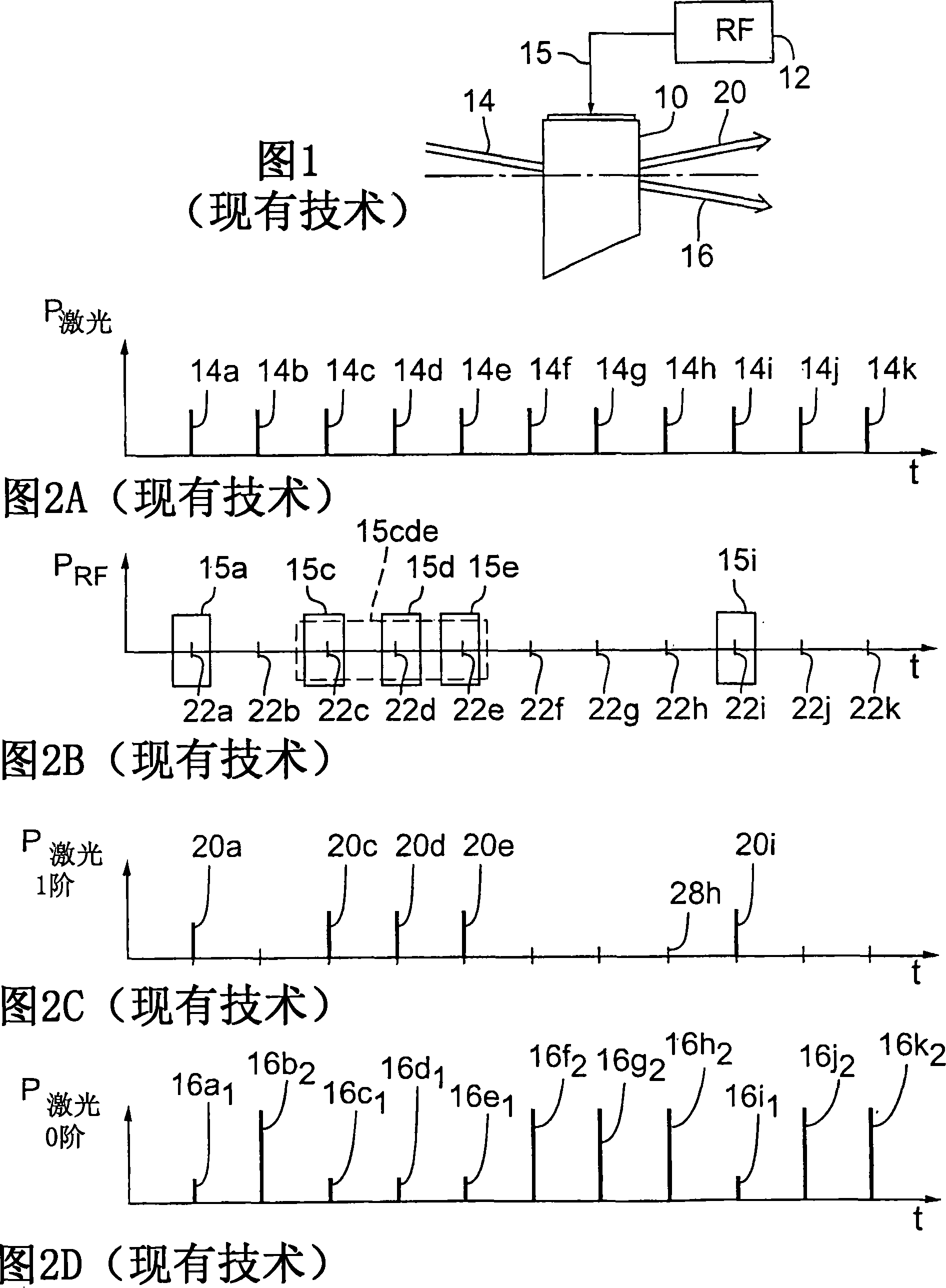
Laser beam mass distortion due to random thermal loads on the AOM 10 can also degrade the laser beam focus, resulting in a larger laser beam spot size at the focused point

Method used


Image

  • Efficient micro-machining apparatus and method employing multiple laser beams
  • Efficient micro-machining apparatus and method employing multiple laser beams
  • Efficient micro-machining apparatus and method employing multiple laser beams

Examples


Embodiment Construction

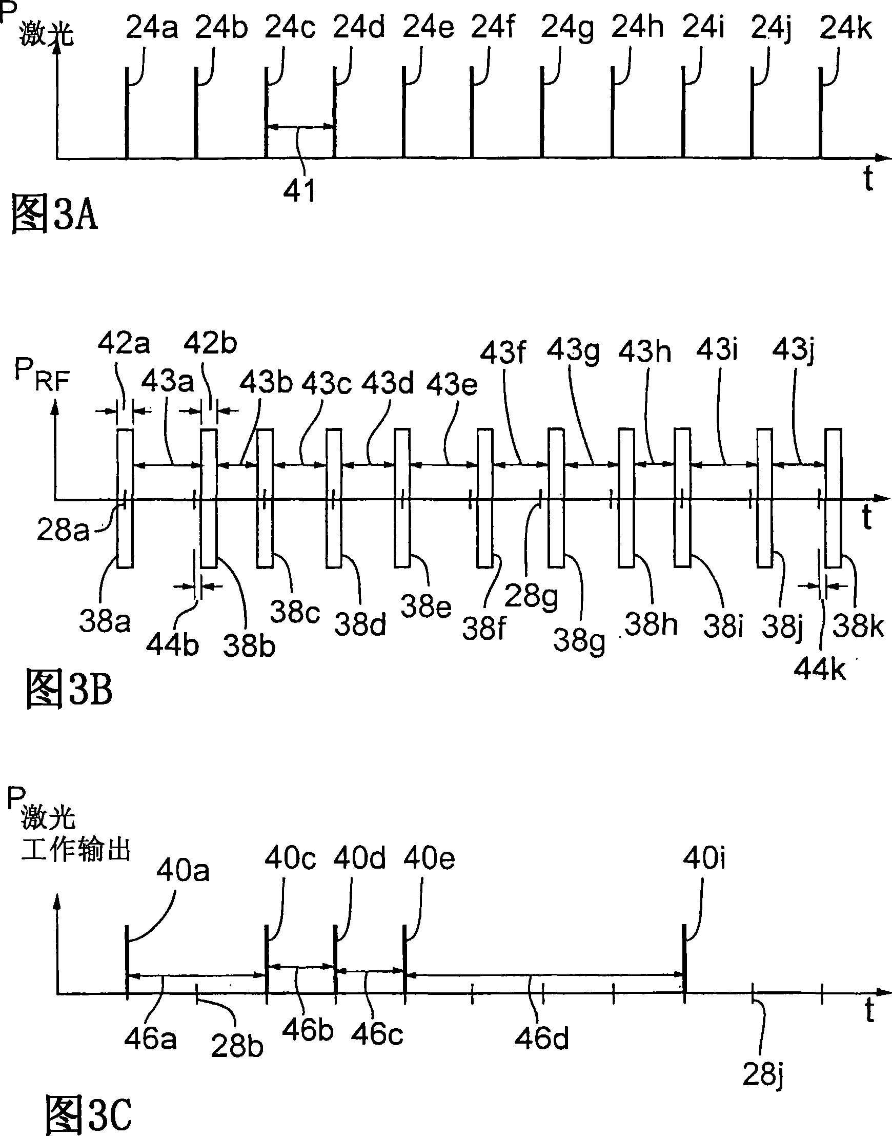
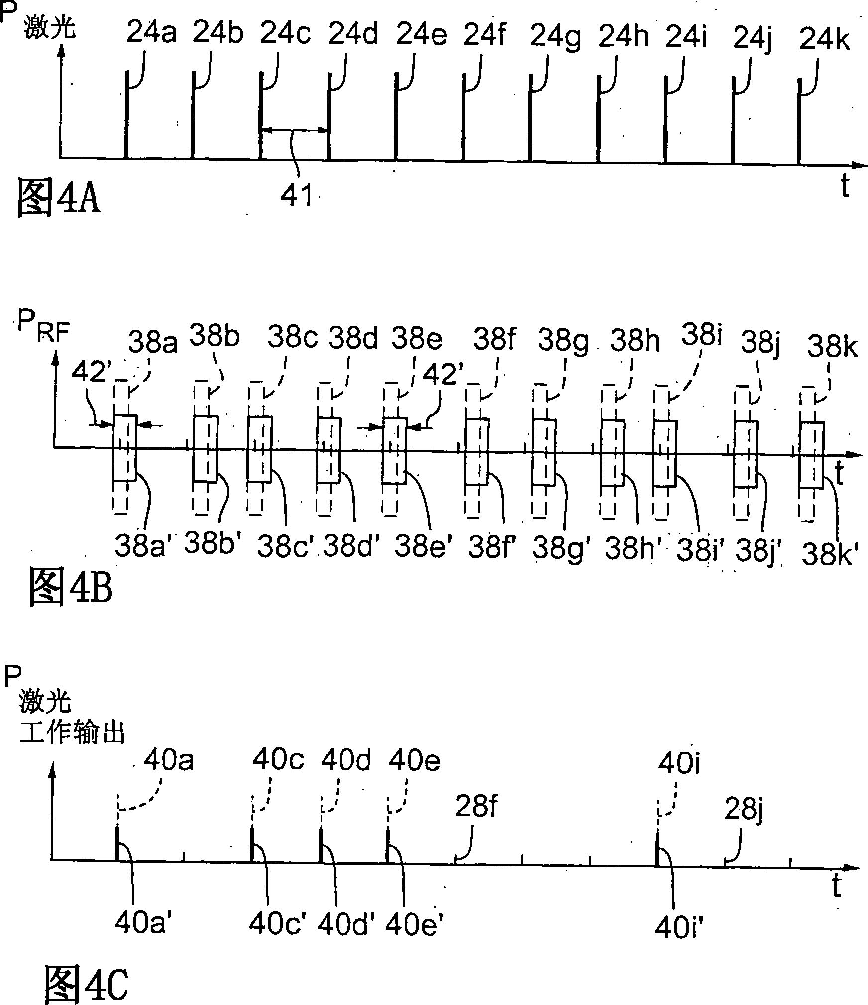
[0043] [0042] By employing the pulse picking and laser power control methods shown with reference to FIGS. 3A-3C and 4A-4C, respectively, thermal load variations in an AOM, such as prior art AOM 10, can be reduced. 3A-3C (collectively FIG. 3 ) illustrate laser outputs 24a-24k (collectively laser outputs 24), RF pulses 38a-38k (collectively RF pulses 38) and working laser outputs applied to prior art AOM 10. Respective timing diagrams of 40a, 40c, 40d, 40e, and 40i (collectively referred to as working laser output 40). Specifically, FIG. 3A shows laser outputs 24a-24k emitted by a laser (not shown) at a fixed repetition rate and separated by substantially equal laser output intervals 41 . In typical embodiments, the laser output repetition rate may range from about 1 KHz to about 500 KHz. Exemplary laser output repetition rates range from about 25 KHz to greater than about 100 KHz. For link processing embodiments, each working laser output 40 preferably includes a single lase...


PUM


Abstract

A workpiece processing system employs a common modular imaged optics assembly and an optional variable beam expander for optically processing multiple laser beams. In one embodiment, a laser and a fixed beam expander cooperate to produce a laser beam that propagates through a beam switching device to produce multiple laser beams that propagate along separate propagation path portions and subsequently merge into a common path portion through an imaged optics assembly and optional variable expander. The beam expander sets the shape of the laser beams in the form of a Gaussian spatial distribution of light energy. The imaged optics assembly shapes the Gaussian spatial distribution of the laser beams to form output beams of uniform spatial distribution. In an alternative embodiment, the beam switching device is removed and the laser beams propagate from separate laser sources associated with separate optional beam expanders.

Description

[0001] related application [0002] [0001] This patent application is a continuation of the following U.S. patent applications: U.S. Patent Application No. 11 / 000,330, filed November 29, 2004, and U.S. Patent Application No. 11 / 000,333, filed November 29, 2004 US Patent Application, the latter application being a continuation of US Patent Application No. 10 / 611,798 filed June 30, 2003. technical field [0003] [0002] The present invention relates to lasers. More particularly, it relates to a method and apparatus for increasing workpiece processing throughput by alternating a single laser beam between two or more beam paths such that one of the beam paths is used to process a workpiece while simultaneously Another beam path is positioned for machining another workpiece. Background technique [0004] [0003] Lasers are widely used in various research fields, development fields, and industrial operations including monitoring, processing, and micromachining various electronic m...

Claims


Application Information

Patent Timeline
Patent Type & Authority Applications(China)
IPC IPC(8): H01L21/26B23K26/064B23K26/066
CPCB23K26/0673B23K26/067
Inventor D·R·卡特拉B·W·伯德R·S·哈瑞斯D·M·海明威H·罗B·E·尼尔森Y·尾峪L·孙Y·孙M·A·安瑞斯
Owner ELECTRO SCI IND INC
Learn More