Temperature and solidification rate real-time monitoring device for polymer based composite material forming process

A composite material and molding process technology, applied in the direction of measuring devices, thermometers with physical/chemical changes, thermometers, etc., can solve the problem of inability to monitor temperature and curing degree simultaneously in real time, low measurement accuracy of small test pieces, and not being widely used, etc. question

Inactive Publication Date: 2008-01-16
HARBIN INST OF TECH
View PDF1 Cites 21 Cited by
  • Summary
  • Abstract
  • Description
  • Claims
  • Application Information

AI Technical Summary

Problems solved by technology

[0007] In order to solve the shortcomings in the prior art that only small-scale test pieces can be measured off-line, low measurement accuracy and high cost, the present invention has not been widely used in actual production, and the temperature in the production process cannot be measured at the same time. Real-time synchronous monitoring with curing degree, so that the heating temperature and heating time cannot be adjusted according to the curing degree, and a real-time synchronous monitoring device for temperature curing degree during the molding process of polymer-based composite materials is proposed

Method used


Image

  • Temperature and solidification rate real-time monitoring device for polymer based composite material forming process
  • Temperature and solidification rate real-time monitoring device for polymer based composite material forming process
  • Temperature and solidification rate real-time monitoring device for polymer based composite material forming process

Examples


specific Embodiment approach 1

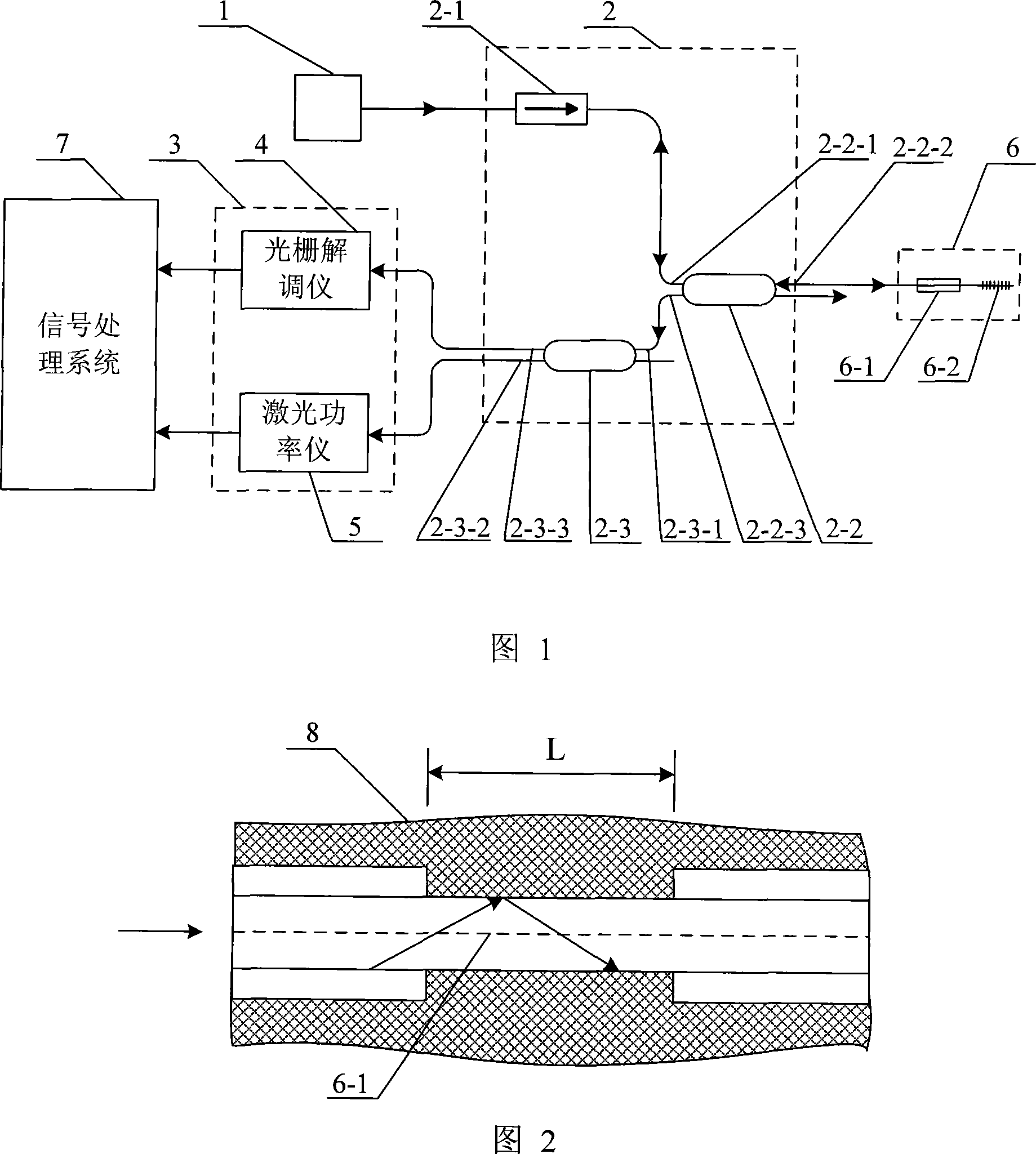
[0011] Specific Embodiment 1: This embodiment is described in conjunction with FIG. 1 and FIG. 2. This embodiment is composed of a laser 1, an optical transmission line assembly 2, an optical receiver 3, a sensing module 6 and a signal processing system 7;

[0012] The optical transmission line assembly is composed of an isolator 2-1, a first coupler 2-2 and a second coupler 2-3, the output end of the laser 1 is connected to the input end of the isolator 2-1, and the isolator 2-1 The output end is connected to the first port 2-2-1 of the first coupler 2-2, the second port 2-2-2 of the first coupler 2-2 is connected to the port of the sensor module 6, and the first coupler 2- The third port 2-2-3 of 2 connects the first port 2-3-1 of the second coupler 2-3, the second port 2-3-2 of the second coupler 2-3 and the third port 2- 3-3 are respectively connected to the two input terminals of the optical receiver 3, and the two output terminals of the optical receiver 3 are respective...

specific Embodiment approach 2

[0013] Specific embodiment two: this embodiment is described in conjunction with Fig. 1, the difference between this embodiment and specific embodiment one is that the optical receiver 3 is made up of a grating demodulator 4 and a laser power meter 5, and the grating demodulator 4 The input end of the input end and the laser power meter 5 are respectively connected to the second port 2-3-2 and the third port 2-3-3 of the second coupler 2-3, the output end of the grating demodulator 4 and the laser power meter The output terminals of 5 are respectively connected to the two data input terminals of the signal processing system 7 . Other compositions and connection methods are the same as those in Embodiment 1.

specific Embodiment approach 3

[0014] Specific embodiment three: This embodiment is described in conjunction with Fig. 1 and Fig. 2. The difference between this embodiment and specific embodiment one is that the distance between the optical fiber refractive index sensor 6-1 and the Bragg grating 6-2 connected in series is 1-2 cm, and other The composition and connection method are the same as those in the first embodiment.


PUM

PropertyMeasurementUnit
wavelengthaaaaaaaaaa

Abstract

The invention relates to a real-time synchronization monitoring device for monitoring the temperature solidification in the formation process of polymer base compound materials. The invention relates to a material formation monitoring device, which solved the problem of the prior technology that only the off-line measuring of the small test sample can be taken and the precision is low and the cost is high, and the real-time synchronous measuring can not be taken. The output terminal of the laser of the invention is connected with the first terminal port of the first coupler through an isolator, the second terminal port of the first coupler is connected with the terminal port of a sensing module, the third terminal port of the first coupler is connected with the first terminal port of the second coupler, and the second terminal port and the third terminal port are separately connected with an optical receiver and two input terminals, the two output terminals of the optical receiver are separately connected with the two input terminals of a signal processing system. One terminal of the optical fiber refractive index sensor in a sensing module is connected with the second terminal port of the first coupler, and the other terminal is connected with the Bragg optical grating. And the sensing module is buried in the material. Online inspecting is adopted, and the heating temperature and the heating time are adjusted according to the solidification; and the product performance and the productivity are enhanced, the production cycle is reduced and the energy is saved and the cost is reduced.

Description

technical field [0001] The invention relates to the technical field of real-time monitoring and analysis of process parameters in the industrial production process, in particular to a material forming monitoring device. Background technique [0002] The forming process of polymer-based composite materials is complex. Macroscopically, it changes from a liquid state to a solid state. Microscopically, linear polymers are polymerized to form a three-dimensional network structure. The heat transfer process and the polymerization reaction are coupled with each other. The curing degree directly affects the physical and chemical properties of the composite material, so it can be used as a characterization index of the composite material performance. During the molding process, if the heating temperature is too high and too fast, the polymerization reaction will be violent, the internal stress of the product will be large, microcracks will easily occur, and the strength will decrease...

Claims


Application Information

Patent Timeline
Patent Type & Authority Applications(China)
IPC IPC(8): G01N21/41G01K11/32G01N25/00G01K11/3206
Inventor 谢怀勤陈幸开刘淼
Owner HARBIN INST OF TECH
Why Eureka
Try Eureka