
Digitized dynamic calibration system for electric turbulent flow sensor

An eddy current sensor, dynamic calibration technology, applied in the direction of the instrument, can solve the problems such as the inability to complete the dynamic response eddy current sensor, the influence of the calibration process, etc., to achieve the effect of increasing the dynamic calibration range, increasing the rotational speed, and simplifying the structure

Inactive Publication Date: 2008-01-23
BEIHANG UNIV
View PDF0 Cites 17 Cited by
  • Summary
  • Abstract
  • Description
  • Claims
  • Application Information

AI Technical Summary

Problems solved by technology

[0006] The problem solved by the technology of the present invention is to overcome the fact that the dynamic calibration system of the existing eddy current sensor cannot complete the dynamic calibration of the eddy current sensor whose dynamic response requires several thousand hertz and higher, and the digitalization degree of data analysis and processing is low, and the calibration process A dynamic calibration system is provided for the dynamic detection and calibration of eddy current sensors, which increases the frequency range of dynamic calibration, improves the detection accuracy, data processing capability and system versatility.

Method used


Image

  • Digitized dynamic calibration system for electric turbulent flow sensor
  • Digitized dynamic calibration system for electric turbulent flow sensor
  • Digitized dynamic calibration system for electric turbulent flow sensor

Examples


Embodiment Construction

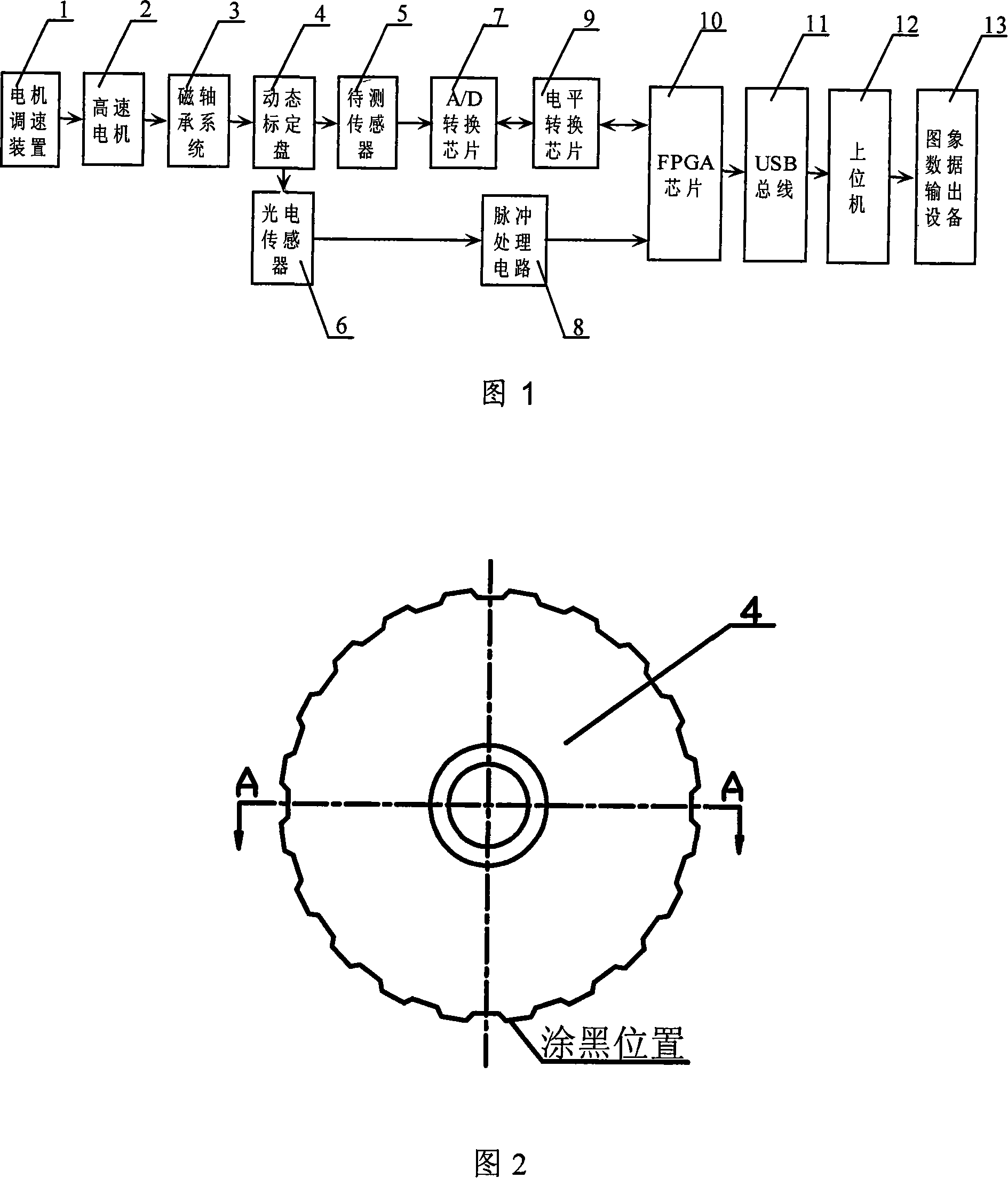
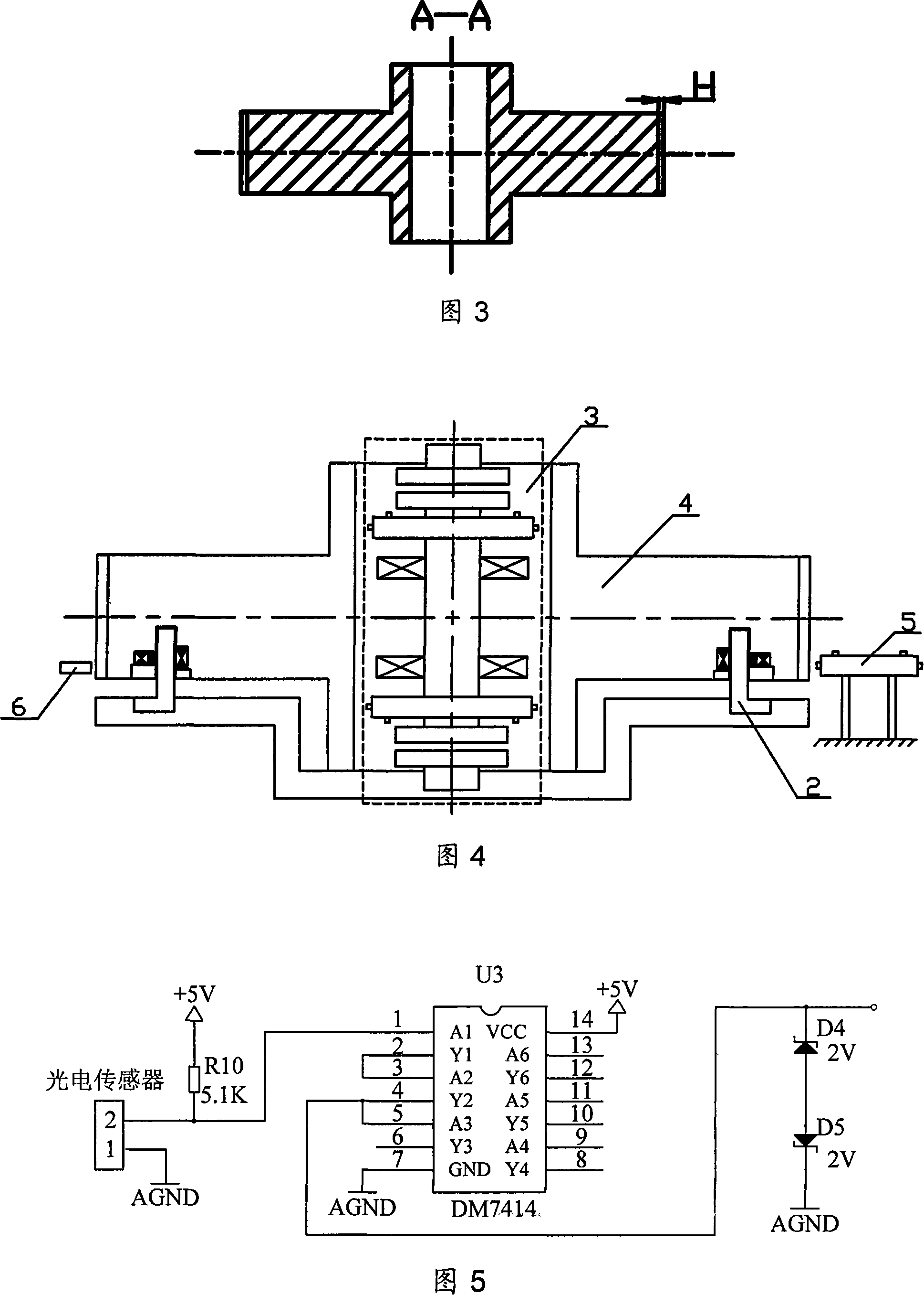
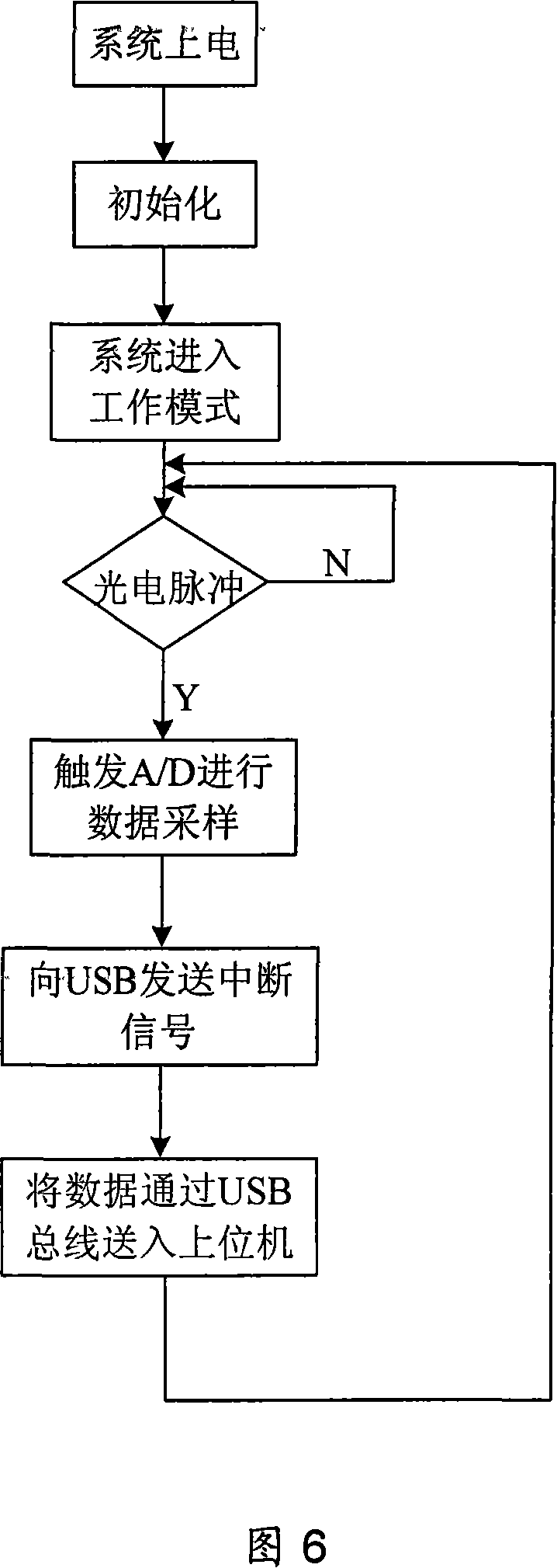
[0023] As shown in Figure 1, the present invention mainly consists of a motor speed control device 1, a high-speed motor 2, a magnetic bearing system 3, a dynamic calibration disk 4, an eddy current sensor to be measured 5, a photoelectric sensor 6, an A / D conversion chip 7, a level It is composed of conversion chip 9 , FPGA chip 10 , USB bus 11 , host computer 12 and image data output device 13 . The motor speed control device 1 is used to control the speed of the high-speed motor 2. The high-speed motor 2 and the magnetic bearing system 3 make the dynamic calibration disk 4 suspend and rotate at high speed, generate high-frequency excitation signals and send them to the sensor 5 to be tested, and the sensor 5 to be tested The high-frequency excitation signal is converted into a high-frequency voltage signal and sent to the A / D conversion chip 7. The A / D conversion chip 7 uses ADS7864Y to sample the high-frequency voltage signal and convert the analog signal into a digital sig...


PUM


Abstract

The invention provides a digital dynamic calibration system for an electric vortex sensor, which is for calibrating dynamically an electric vortex sensor, and is essentially comprises a hi-speed motor, a magnetic bearing system, a dynamic calibrating disc, an A / D conversion chip, a FPGA chip, a USB bus and an up-level unit. The magnetic bearing system, in conjunction with the hi-speed motor, drives the dynamic calibrating disc to rotate at high speed, generate hi-frequency excitation signals to be input to the sensor to be measured. A photoelectric sensor senses the reference position on the dynamic calibrating disc, generates a reference pulse signal for triggering the A / D conversion chip controlled by the FPGA chip to carry out data sampling of the output signals from the sensor, which first go through A / D conversion by the A / D conversion chip, then are sent into the FPGA chip for data acquisition and processing, sent to the up-level unit through the USB bus; finally the indexes on the dynamic frequency of the electric vortex sensor are got. The invention is especially applicable for the dynamic calibration of the electric vortex sensors used in maglev systems.

Description

technical field [0001] The invention relates to a dynamic calibration system of an eddy current sensor, which is used for dynamic testing and calibration of an eddy current sensor, and is especially suitable for calibrating the dynamic frequency response of an eddy current displacement sensor for non-contact measurement of high-speed rotor displacement in a magnetic bearing system Parameters, such as spacecraft attitude control mechanism magnetic levitation flywheel, eddy current sensor for magnetic levitation gyro. Background technique [0002] The eddy current sensor uses the eddy current effect to make the coil with the high-frequency AC signal generate an alternating magnetic field, and the surface of the measured conductor placed in this alternating magnetic field will generate an eddy current, and this eddy current effect will cause the electrical parameters of the sensor probe coil Changes, with the corresponding measurement circuit, the displacement, vibration, thick...

Claims


Application Information

Patent Timeline
Patent Type & Authority Applications(China)
IPC IPC(8): G01D18/00
Inventor 刘刚房建成张倩田希晖
Owner BEIHANG UNIV
Learn More