
LED lamp heat radiation method applying cross-ventilation warehouse

A technology of LED lamp and heat dissipation method, which is applied to the cooling/heating device of lighting device, lighting and heating equipment, components of lighting device, etc. weight loss effect

Inactive Publication Date: 2008-02-06
王其林
View PDF0 Cites 19 Cited by
  • Summary
  • Abstract
  • Description
  • Claims
  • Application Information

AI Technical Summary

Problems solved by technology

However, air convection heat dissipation is a forbidden area for LED lamps. In order to prevent air from entering LED lamps and protect circuits and electrical components from oxidation and corrosion, almost all adopt sealing methods, emphasizing waterproof performance, which makes heat dissipation difficult.

Method used


Image

  • LED lamp heat radiation method applying cross-ventilation warehouse
  • LED lamp heat radiation method applying cross-ventilation warehouse
  • LED lamp heat radiation method applying cross-ventilation warehouse

Examples


Embodiment 1

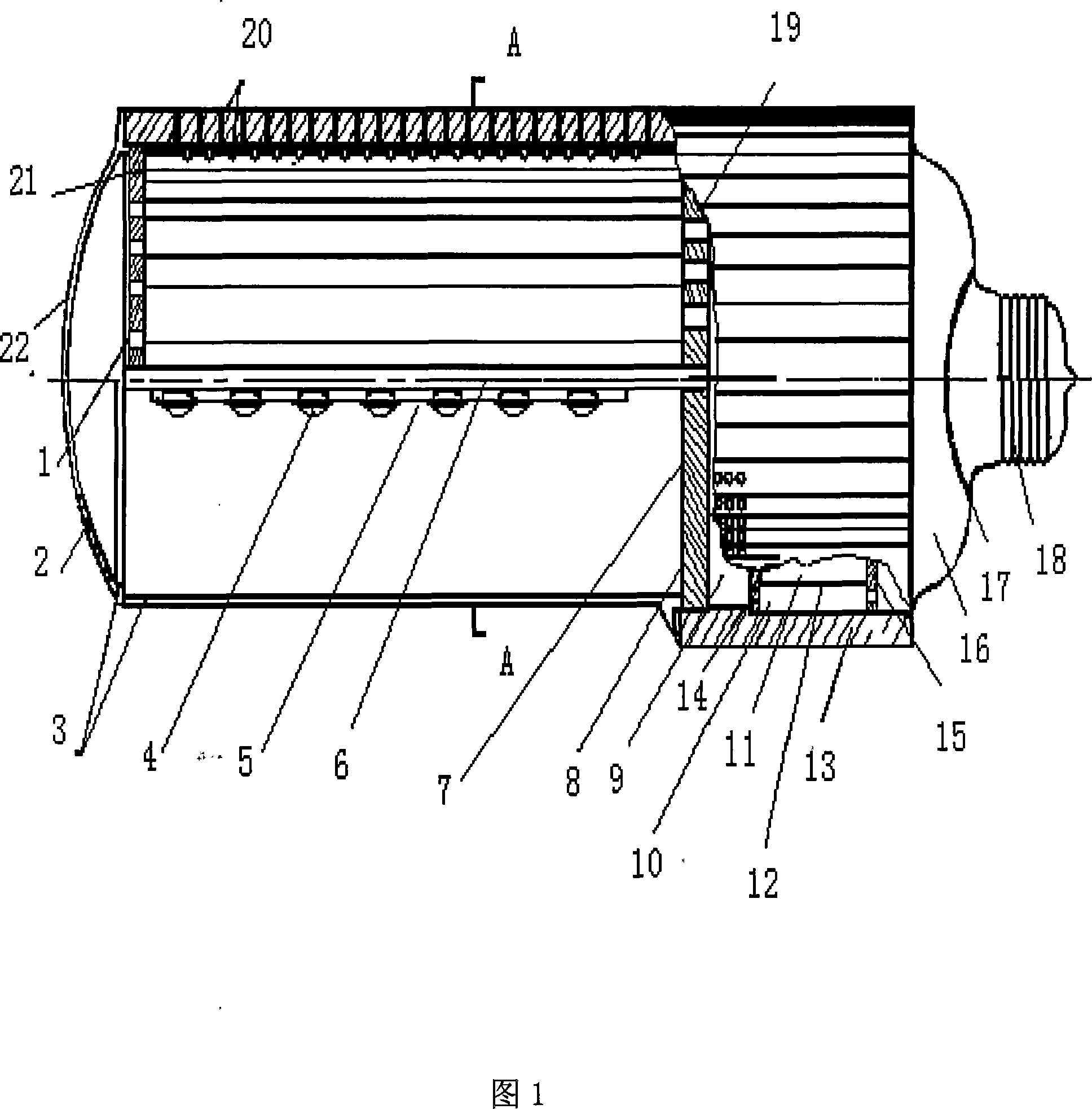
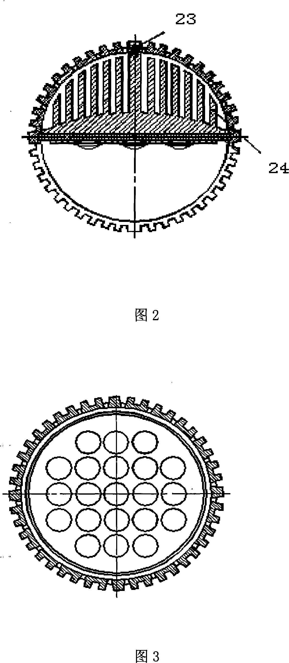
[0027] In this embodiment, a 21W horizontal LED lamp is taken as an example, as shown in Figures 1 and 2. The horizontal LED lamp with an air convection chamber described in the utility model is composed of a housing 13 with a heat dissipation function, a power supply and a constant current source. Composed of circuit board 11, LED illuminant 4, circuit board 5, aluminum heat sink, inner heat sink, lamp cover 16, lamp holder 18, and outer cover 3;

[0028]The rear half of the outer surface of the housing 13 with heat dissipation function is a concave-convex rectangular-toothed cylinder, the front half is a concave-convex rectangular-toothed half-cylinder, and the joint between the cylinder and the semi-cylinder is provided with a circular shape with the same diameter as the cylinder. The aluminum cooling plate 7, the part where the circular aluminum cooling plate 7 is connected with the semi-cylinder is provided with an air inlet 19, the cylinder is provided with an air inlet 8...

Embodiment 2

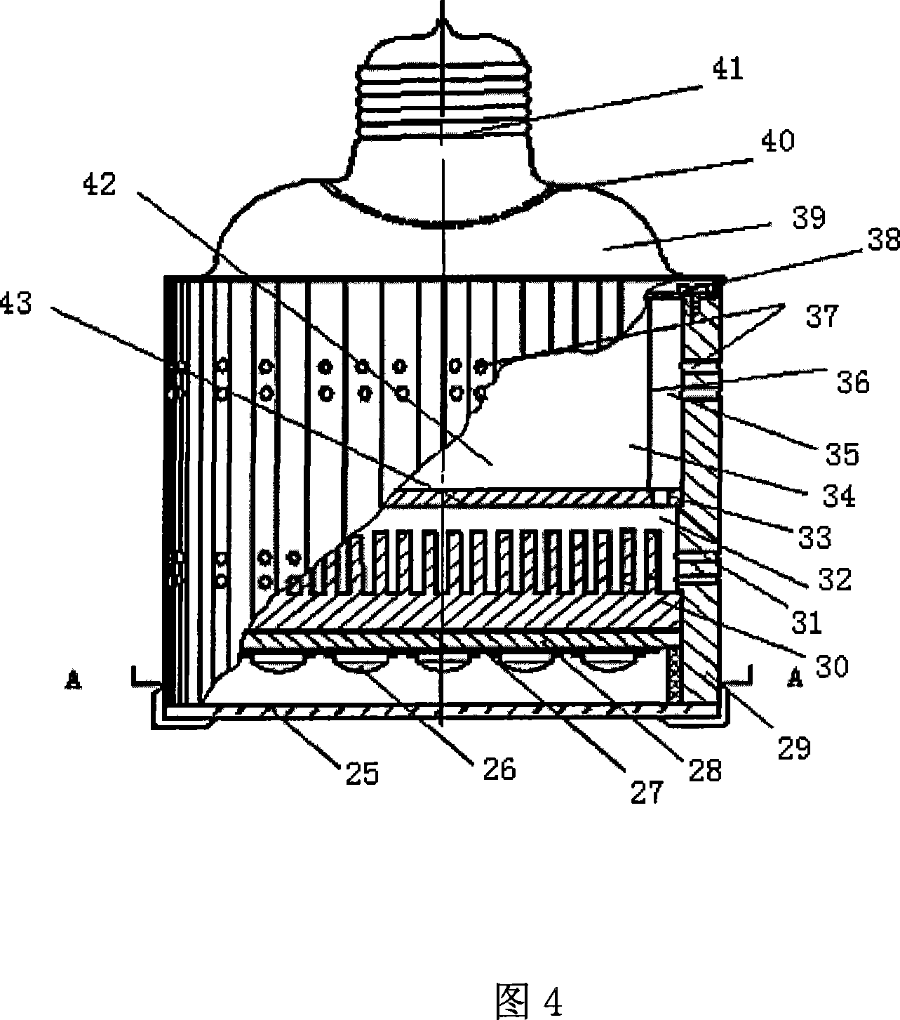
[0030] In this embodiment, a 21W straight LED lamp is taken as an example, see Figs. 3 and 4, and the structure of the straight LED lamp with an air convection chamber is described in detail.

[0031] The straight LED lamp with air convection chamber described in this embodiment is composed of a housing 29 with heat dissipation function, a circuit board 34 integrating a power supply and a constant current source, an LED illuminant 26, a circuit board 27, and three aluminum heat dissipation plates. , a cylindrical aluminum heat sink 36, and an inner heat sink 30; the housing 29 with heat dissipation function is composed of a conical, cylindrical, elliptical or rectangular pipe body with a concave-convex rectangular tooth shape on the outer surface, and openings on the walls around the lower end There are two rows of a total of 36 round holes as the air intake holes 31, and two rows of a total of 36 round holes are arranged on the wall around the upper end as the air outlet holes...

Embodiment 3

[0033] The integrated circuit board circuit structure of power supply and constant current source of the present invention is as follows:

[0034] The constant current source circuit is as follows:

[0035] Pin 1 of resistor R2 is connected to the positive pole of the LED luminous body, and connected to the positive pole of +24V power supply; pin 2 of resistor R2 is connected to the connection point of pin 2 of transistor Q2 and pin 1 of transistor Q3; pin 1 of transistor Q2 is connected to the resistor Pin 1 of R6 is connected to pin 3 of transistor Q3, pin 1 of resistor R7 is connected to the connection point of pin 1 of transistor Q2 and pin 3 of transistor Q3; pin 3 of transistor Q2, pin 2 of resistor R6, resistor R7 Pin 2 of the triode Q3 is connected to the negative pole of the LED luminous body;

[0036] The power supply circuit is as follows:

[0037] Pin 1 of capacitor C1 is respectively connected to pin 1 of eddy current coil T1 and mains +220V; pin 2 of capacitor ...


PUM


Abstract

The present invention relates to a radiating method of a LED lamp of an air convection bin. The present invention is characterized in that an air convection bin and an air convection channel are arranged around a circuit board, a power source and a constant current source in a LED lamp casing body; the air convection bin is composed of radiating plates and the air convection channel is composed of the radiating plate and the casing body, a ventilation hole is arranged on the radiating plate, a matched air input hole and an air output hole are arranged on the casing body, the radiating structure which is formed by the radiating plate and the radiating slice is arranged in the air convection bin and at the periphery of the air convection bin, cold air current can enter into the casing body, the heat produced by the circuit board, the power and the constant current source during working is brought out of the casing body by the cold air current which passes through the air convection bin and the air current channel and passes through the cold-hot exchange of the cooling plate and the cooling slice, achieving the purpose of cooling; the air convection bin can carry away 25 percent heat in the casing body, thereby removing the accumulate effect of the heat during the LED lamp luminescence, and effectively solving the problems that the cooling of the high-power LED lamp is difficult, the cast is expensive and the LED lamp can not be commonly used.

Description

technical field [0001] The invention relates to a heat dissipation method for a semiconductor LED (Lingt emitting diode) lamp using an air convection chamber. Background technique [0002] LED lights have low power consumption and have a huge energy-saving effect. A 100W energy-saving lamp with a height of 8 meters from the ground, an illuminance of 30LUX, and a luminous flux of 4800LM. One-twentieth to one-thirtieth. LED also has the advantages of long life, small size, and strong design (that is, to realize the random arrangement of illumination light). In the past ten years, many countries in the world have invested huge sums of money in order to further develop the potential advantages of LED and realize the industrialization technology of high-power and high-efficiency LED chip production technology. Such as Japan in 1998, the United States in 2000 have launched the "National Semiconductor Lighting Program." In 2001, my country's 863 plan was established, and in Jun...

Claims


Application Information

Patent Timeline
IPC IPC(8): F21V29/00F21V29/02F21V17/00F21Y101/02F21V29/503F21V29/60F21V29/83F21Y115/10
Inventor 王其林
Owner 王其林
Learn More