

Single runner two stage dehumidify air-conditioner driven by solar
A rotary dehumidification and solar energy technology, applied in air conditioning systems, space heating and ventilation, household heating, etc., can solve problems such as difficulties, high regeneration temperature, and limited dehumidification capacity, and achieve low equipment investment costs and excellent energy efficiency , the effect of simple structure
- Summary
- Abstract
- Description
- Claims
- Application Information
AI Technical Summary
Problems solved by technology
Method used
Image

Examples
Embodiment 1
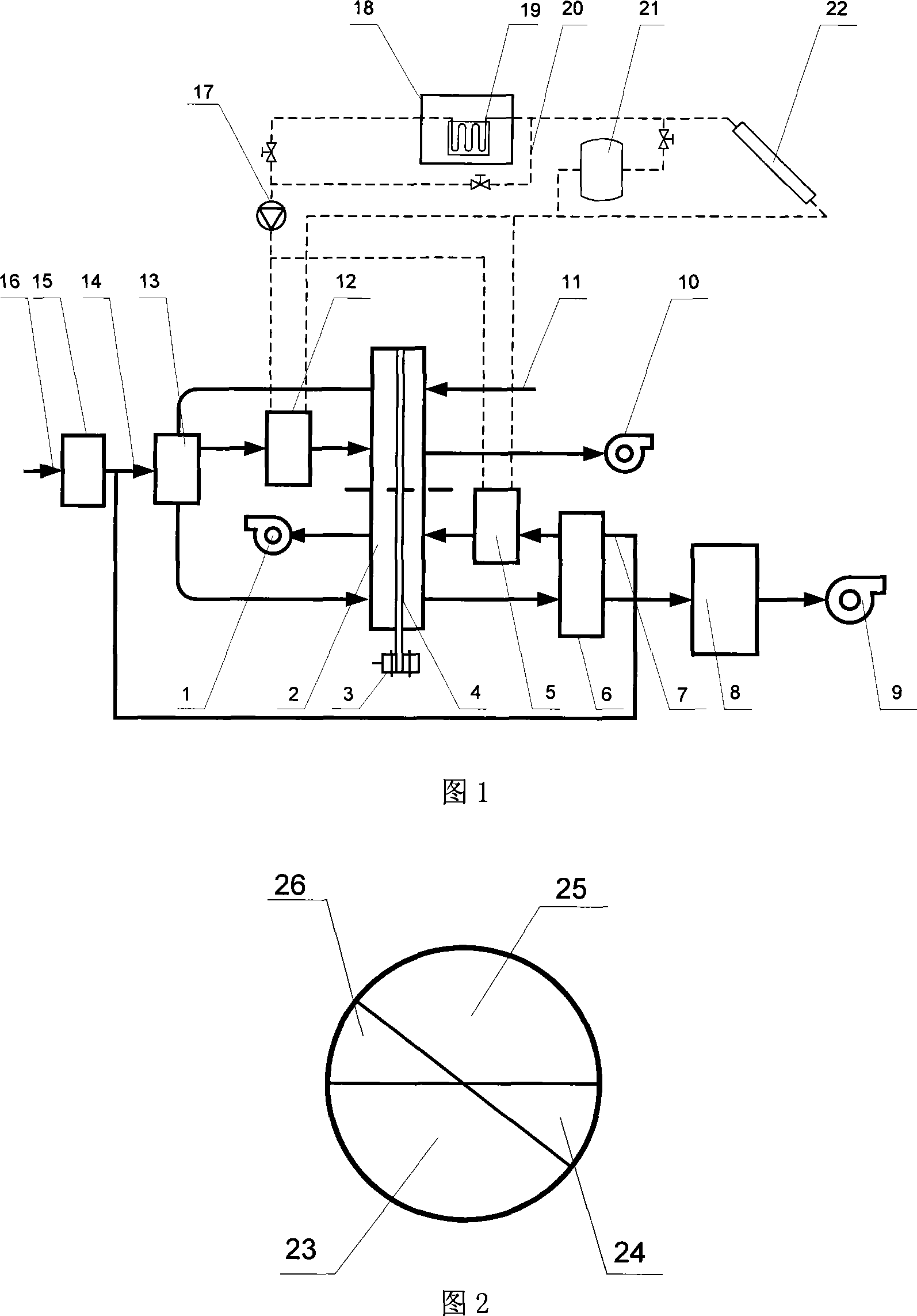
[0030] As shown in Figure 1, it is a single-wheel two-stage desiccant air conditioner driven by solar hot water.
[0031] This embodiment includes: a second-stage regenerative fan 1, a dehumidification runner 2, a runner drive motor 3, a runner drive belt 4, a second-stage regeneration heater 5, a second-stage treatment heat exchanger 6, and a second-stage regeneration Air inlet duct 7, evaporative cooler 8, treatment fan 9, first-stage regeneration fan 10, treatment air inlet duct 11, first-stage regeneration heater 12, first-stage treatment heat exchanger 13, first-stage regeneration Air inlet duct 14, regeneration side evaporative cooler 15, regeneration air inlet main pipe 16, hot water pump 17, hot water tank 18, hot water heat exchanger 19, water tank bypass pipe 20, auxiliary heater 21, solar collector twenty two.
[0032]As shown in FIG. 2 , the structure schematic diagram of the desiccant wheel with two partitions, the first-stage treatment area 23 , the first-stage ...
Embodiment 2
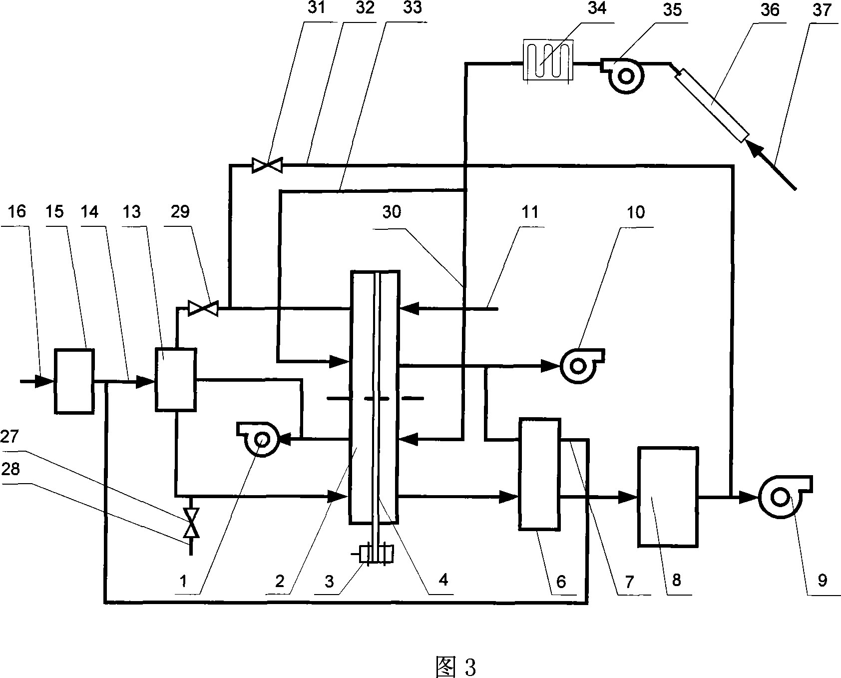
[0042] As shown in Figure 3, it is a single-wheel two-stage desiccant air conditioner driven by solar hot air, which is used for air conditioning and cooling in summer.
[0043] As shown in Fig. 3, this embodiment includes: the second-stage regenerative fan 1, the dehumidification runner 2, the runner drive motor 3, the runner drive belt 4, the second-stage treatment heat exchanger 6, the second-stage cooling air inlet air Pipe 7, evaporative cooler 8, processing fan 9, first stage regeneration fan 10, processing air inlet duct 11, first stage processing heat exchanger 13, first stage cooling air inlet duct 14, cooling air evaporative cooler 15. Cooling air inlet main pipe 16, second-stage processing air inlet air valve 27 in winter, second-stage processing air inlet duct 28 in winter, intermediate valve 29 for processing air, second-stage regeneration air pipe 30, and bypass valve 31 for processing air , Handle wind side air duct 32, first stage regeneration air duct 33, auxi...
Embodiment 3
[0054] This embodiment is used for heating in winter, and the structure is shown in Figure 3. The difference from Embodiment 2 is that the structure of this embodiment does not include: the first stage processing heat exchanger 13, the first stage cooling air inlet duct 14, the cooling air evaporative cooler 15, the cooling air inlet main pipe 16, the second stage Dealing with heat exchanger 6, evaporative cooler 8, they are not working in this embodiment.
[0055] The winter heating method of the two-stage desiccant dehumidification air conditioner realized by the above structural features is:
[0056] In winter, the air valve 27 of the second-stage treatment air inlet is opened, the treatment air bypass valve 31 is opened, and the treatment air intermediate valve 29 is closed. Outdoor air or indoor return air, or indoor and outdoor mixed wind (regeneration air for short) ambient air is driven by the hot air fan 35 and enters the solar air heat collector 36 through the heat ...
PUM
 Abstract
Description
Claims
Application Information