
Microbiological fuel cell device and battery and use and water treatment system

A technology of fuel cells and microorganisms, which is applied in the field of sewage treatment systems and microbial fuel cells, and can solve the problems of low proton migration efficiency

Inactive Publication Date: 2008-02-06
BYD CO LTD
View PDF2 Cites 37 Cited by
  • Summary
  • Abstract
  • Description
  • Claims
  • Application Information

AI Technical Summary

Problems solved by technology

[0007] The purpose of the present invention is to overcome the shortcoming of low proton transfer efficiency in prior art microbial fuel cells, and provide a microbial fuel cell device capable of improving the proton transfer efficiency of microbial fuel cells

Method used


Image

  • Microbiological fuel cell device and battery and use and water treatment system
  • Microbiological fuel cell device and battery and use and water treatment system
  • Microbiological fuel cell device and battery and use and water treatment system

Examples


Embodiment 1

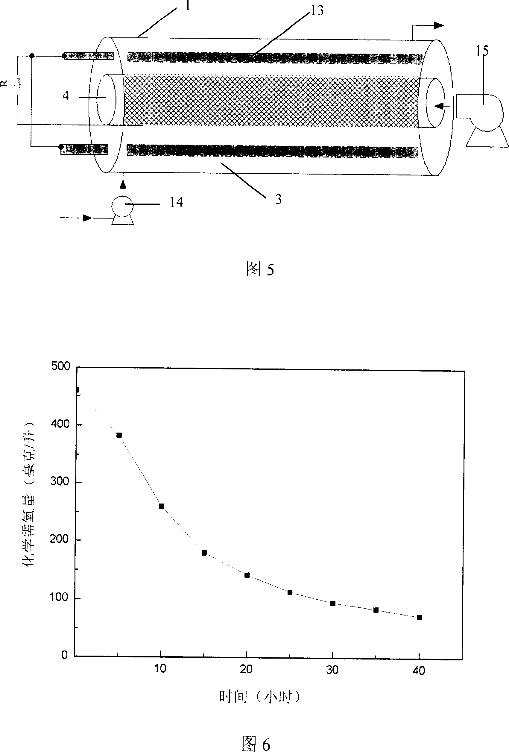
[0057] This embodiment illustrates the microbial fuel cell device provided by the present invention, the microbial fuel cell with the device, the use method of the cell, and the sewage treatment system including the cell.

[0058] (1) Preparation of microbial fuel cell device

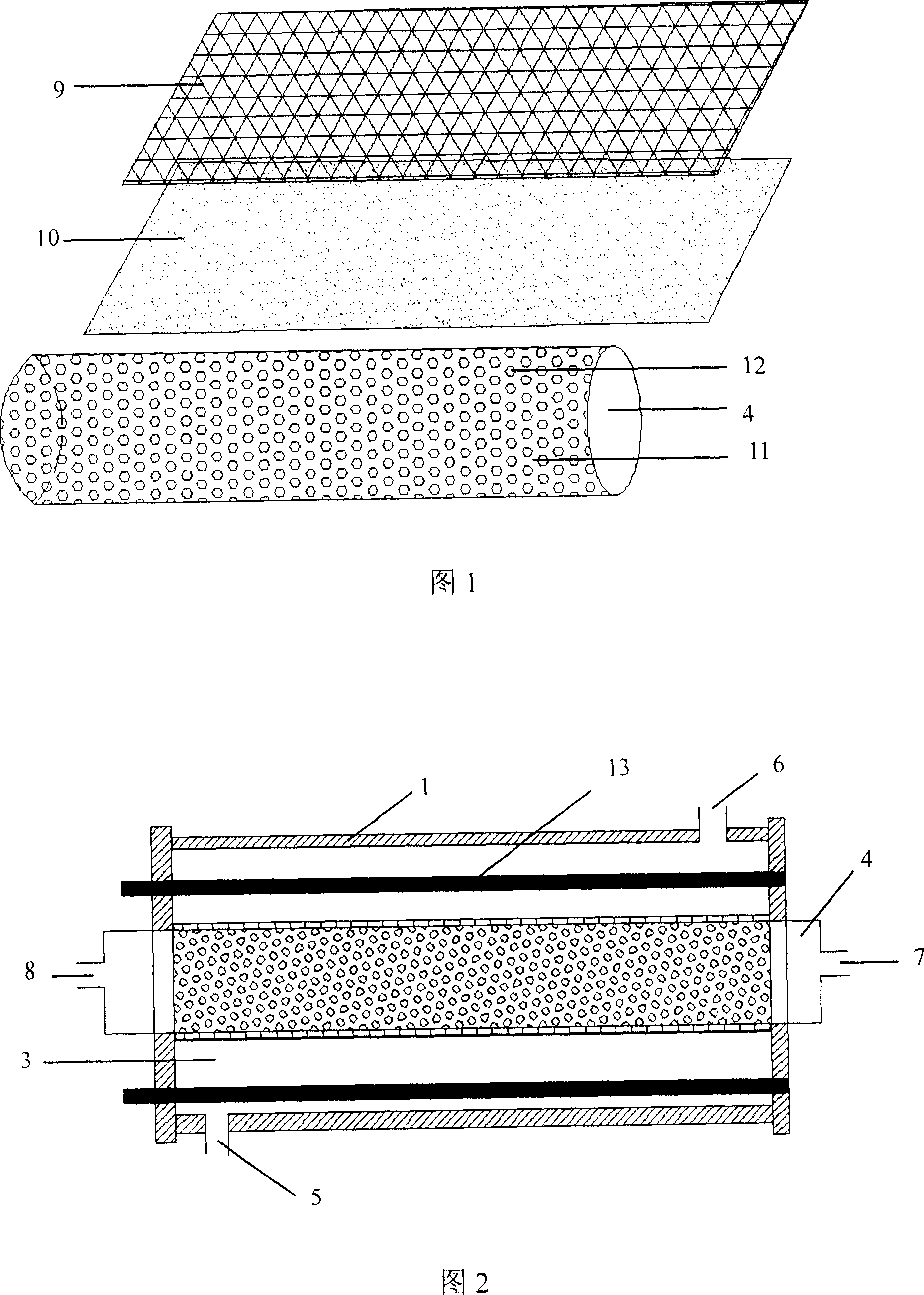
[0059] As shown in Figure 1, the carbon cloth, Nafion117 film and stainless steel mesh with the same area as the outer surface of the cylinder wall of the inner cylinder bracket 11 are pressed sequentially on the outer surface of the cylinder wall of the cylindrical plexiglass inner cylinder bracket 11 to form an inner Cylinder wall. The surface area of ​​the sheet cathode (carbon cloth) is 100% of the surface area of ​​the diaphragm (ie Nafion 117 proton exchange membrane), and the two are bonded together to form the membrane cathode assembly 10 . The inner cylinder support 11 has an inner diameter of 4 cm, a length of 50 cm, a wall thickness of 2 mm, and mesh holes 12 with a diameter of 2 mm evenly d...

Embodiment 2

[0068] This embodiment illustrates the microbial fuel cell device provided by the present invention, the microbial fuel cell with the device, the use method of the cell, and the sewage treatment system including the cell.

[0069] 1) Preparation of microbial fuel cell device

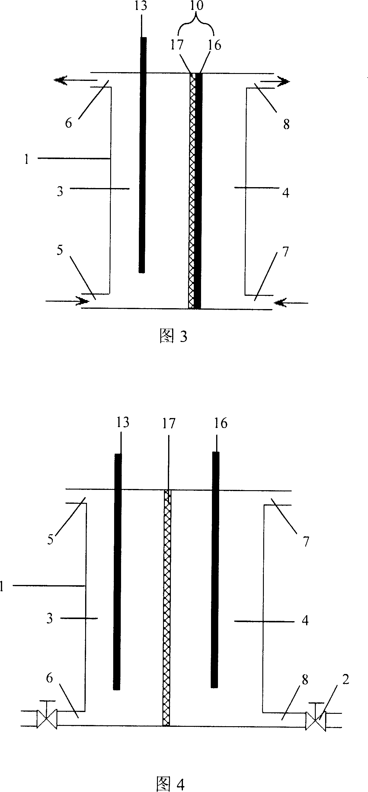
[0070] First press Nafion117 film and cathode carbon paper to obtain membrane cathode assembly 10, the size of this membrane cathode assembly is 20 centimeters * 20 centimeters, wherein, the area of ​​sheet cathode (carbon paper) surface is diaphragm (being Nafion117 proton exchange membrane) surface 90% of the area. As shown in Figure 3, use glass glue to bond plexiglass to prepare a battery case 1 of 20 centimeters x 20 centimeters x 30.75 centimeters, and use the cathode assembly 10 and the battery case to form a cuboid anode chamber 3 and cathode chamber with a volume ratio of 2:1 Room 4. The volume of the anode chamber of the obtained microbial fuel cell device is the same as that of the anode cha...


PUM


Abstract

A microorganism fuel cell device comprises an outer cover(1) of the fuel cell, an anode chamber(3), an anode(13), a cathode chamber(4), a cathode(16) and a septum(17). Wherein, the anode(13) is positioned inside the anode chamber(3); the septum(17) is positioned between the anode chamber(30) and the cathode chamber(4). The cathode(16) is a slice-shaped cathode, one surface of the slice-shaped cathode and one surface of septum(17) are jointed to form a septum cathode component(10); the surface of slice-shaped cathode not jointing with the septum(17) is positioned at one side of the cathode chamber(4). As the disclosed microorganism fuel cell device forms the septum cathode component by jointing the slice-shaped cathode with the septum, the invention further improves the moving efficiency of the media and also speeds up the cathode reaction, so that the overall reacting speed of the microorganism fuel cell for the device is greatly improved. Therefore, the invention can realize the large scaled successive disposal of the waste water.

Description

technical field [0001] The present invention relates to a fuel cell device and a battery with the device, as well as a method for using the battery and a sewage treatment system including the battery, in particular to a microbial fuel cell device and a microbial fuel cell with the device, and The use method of the battery and the sewage treatment system including the battery. Background technique [0002] Water source pollution is the most harmful and widespread pollution. For the purpose of protecting the environment, pollutants, especially sewage, must meet the national pollutant discharge standards, so sewage must be treated. Sewage treatment methods include physical treatment, chemical treatment, physicochemical treatment, biological treatment and combinations thereof. At present, sewage with high chemical oxygen demand (COD) value rich in organic matter is mainly treated centrally through sewage treatment plants using biological treatment methods. The most commonly us...

Claims


Application Information

Patent Timeline
IPC IPC(8): H01M8/16C02F3/00
CPCY02E60/527Y02E60/50
Inventor 董俊卿
Owner BYD CO LTD
Learn More