Cantilever type high rate turbine vacuum pump and its evacuation method

A vacuum pump and cantilever technology, which is used in the field of vacuum equipment and turbo machinery, can solve the problems of difficult to achieve high speed and large volume, and achieve the effects of high mechanical efficiency, reduced energy consumption, and efficient extraction.

Active Publication Date: 2008-02-13
ZHEJIANG UNIV +1
View PDF0 Cites 16 Cited by
  • Summary
  • Abstract
  • Description
  • Claims
  • Application Information

AI Technical Summary

Problems solved by technology

[0009] Based on the above ideas, German MAN company has specially designed and provided single-stage and multi-stage vacuum fans TURBAIR for the dehydration process according to the technological characteristics of paper mills. It uses closed c

Method used


Image

  • Cantilever type high rate turbine vacuum pump and its evacuation method

Examples


Embodiment 1

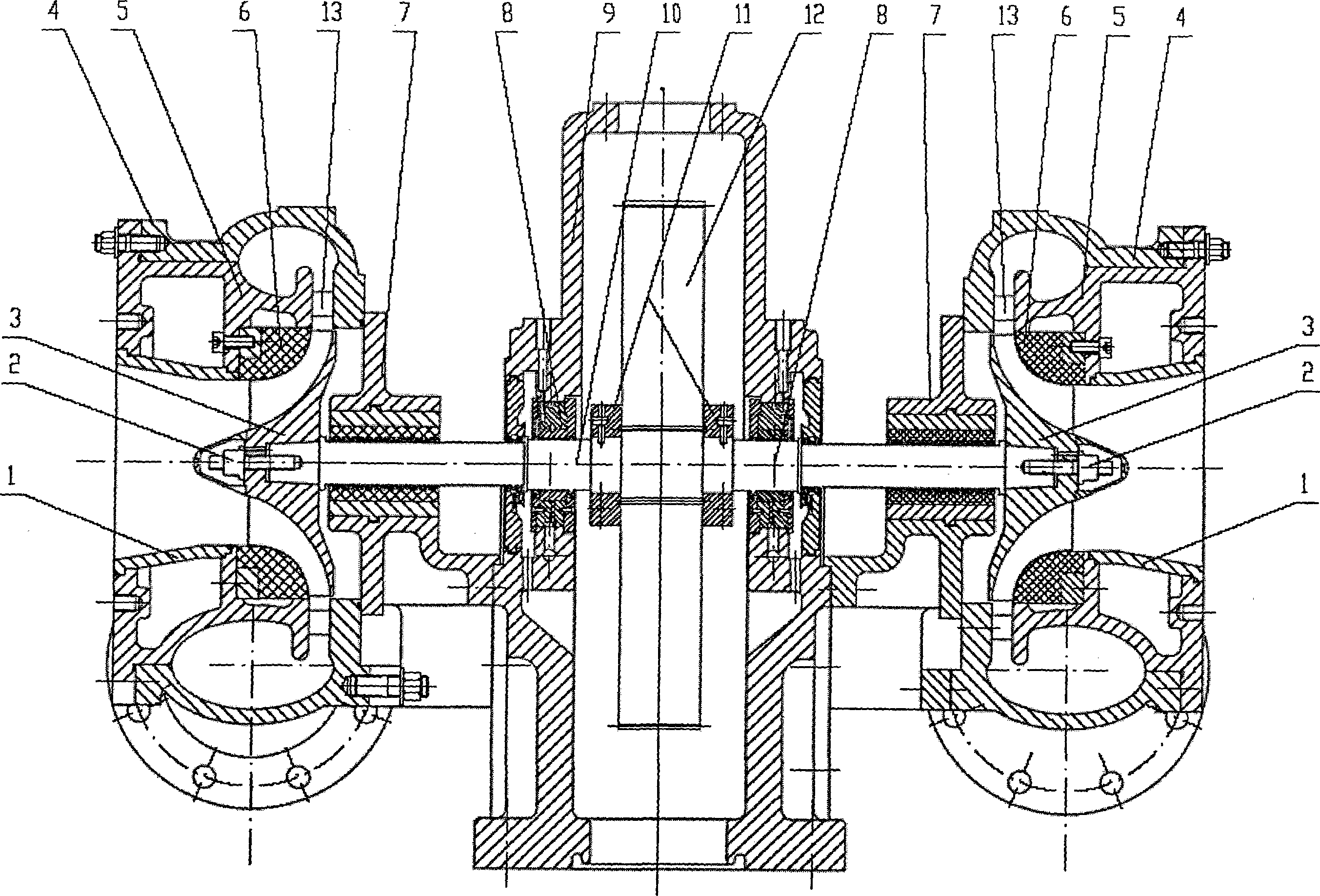
[0031] The cantilever type high-speed turbo vacuum pump of this embodiment has a detailed structure as shown in the accompanying drawings. It includes a gear speed-up box 9, two independent pump heads and a high-speed rotor. The gear speed-up box 9 adopts a single-stage speed-up, and the large gear The shaft on 12 is connected with the prime mover; two independent pump heads are separated on both sides of the gear speed increaser box 9, and are in a symmetrical structure. The cover 6, the volute 4 and the air seal 7, the suction port 1 and the impeller static wheel cover 6 are installed on the inner body of the volute 5 to form an integral body embedded in the volute 4, which is formed by the combination of the inner body 5 of the volute and the cavity of the volute 4 Diffuser and medium outflow channel, air seal 7 are installed on the side of volute 4 through flange; The sliding bearing 8 on the top is supported and driven by the bull gear 12. The thrust plate 11 is fixedly i...

Embodiment 2

[0039] The cantilever type high-speed turbo vacuum pump of this embodiment has a detailed structure as shown in the accompanying drawings. It includes a gear speed-up box 9, four independent pump heads and two high-speed rotors. The gear speed-up box 9 adopts a single-stage speed-up, The shaft on the large gear 12 is connected to the prime mover; the four independent pump heads are separated on both sides of the gear speed increaser box 9, and the two on each side have a symmetrical structure. Body 5, impeller stationary wheel cover 6, volute 4 and air seal 7, suction port 1 and impeller stationary wheel cover 6 are installed on the volute inner body 5 to form an integral body embedded in the volute 4, composed of the volute inner body 5 and the volute The cavity of the casing 4 is combined to form a diffuser and a medium outflow channel, and the air seal 7 is installed on the side of the volute 4 through a flange; the high-speed rotor includes a high-speed gear shaft 10, a thr...


PUM


Abstract

The invention discloses a cantilever-type high-speed vacuum turbine pump and the vacuum pumping method. A high-speed eccentric impeller of 10000 revolutions per minute to 30000 revolutions per minute is used to realize the pumping of vacuum with minus 30kPa to minus 70kPa. The pump comprises a gear increase box, independent pump heads and a high-speed rotor. A large gear of the gear increase box is connected with a prime motor. Independent pump heads stand separately at both sides or a single side of the gear increase box. The pump heads adopt a split structure and comprise a suction inlet, an internal volute body, an impeller stopping cover, a volute shell and an air seal. The high-speed rotor comprises a high-speed gear shaft, a thrust collar, an impeller, and a fastening bolt, and is supported by a sliding bearing on the gear increase box. An impeller cantilever is arranged on the tail end of the high-speed gear shaft. The invention uses a high-speed turbine to realize the rapid vacuum pumping with a large flow. Moreover, a multi-pump head structure can make a single pump realize the multi-position, multi-vacuum degree and simultaneous pumping in the fields of paper making, chlor-alkali chemical industry, and so on and greatly reduce the vacuum system energy consumption. Meanwhile, the pump is provided with the advantage that the pump is concise in the structure, highly reliable, widely applicable, and environment-friendly, and does not need a liquid working ring, and so on.

Description

technical field [0001] The invention relates to a vacuum pump, more specifically a cantilever type high-speed turbo vacuum pump and a vacuum pumping method thereof, which belong to the technical field of vacuum equipment and turbo machinery. Background technique [0002] Vacuum pumps usually form a vacuum system with other equipment, and are widely used in petroleum, chemical, machinery, mining, light industry, medicine, food, electronics, metallurgy, aerospace and other departments. Traditional vacuum pump products that are widely used mainly include liquid ring vacuum pumps, reciprocating Type vacuum pump, Roots vacuum pump and rotary vane vacuum pump, etc. [0003] Among them, the liquid ring vacuum pump is a rough vacuum pump and can also be used as a compressor. It is widely used in industrial production processes such as vacuum filtration, vacuum water diversion, vacuum feeding, vacuum evaporation, vacuum concentration, vacuum moisture regain and vacuum degassing. app...

Claims


Application Information

Patent Timeline
IPC IPC(8): F04D17/10F04D25/02F04D29/42F04D29/44F04D29/28F04D29/056F04D29/30
Inventor 吴大转温建新王乐勤
Owner ZHEJIANG UNIV
Why Eureka
Try Eureka