Switching loss reduced single-stage power factor correcting circuit

A power factor correction, switching loss technology, applied in the output power conversion device, the conversion of DC power input to DC power output, electrical components and other directions, can solve the problem of increasing leakage inductance loss, large current, etc.

Inactive Publication Date: 2008-03-05
ZHEJIANG UNIV
View PDF2 Cites 17 Cited by
  • Summary
  • Abstract
  • Description
  • Claims
  • Application Information

AI Technical Summary

Problems solved by technology

However, when the switch tube SW is turned on, the inductor L P current and winding N 1 The current flows through the winding N 2 , the current of this winding is larger; when the switch tube SW is disconnected,

Method used


Image

  • Switching loss reduced single-stage power factor correcting circuit
  • Switching loss reduced single-stage power factor correcting circuit
  • Switching loss reduced single-stage power factor correcting circuit

Examples


Embodiment Construction

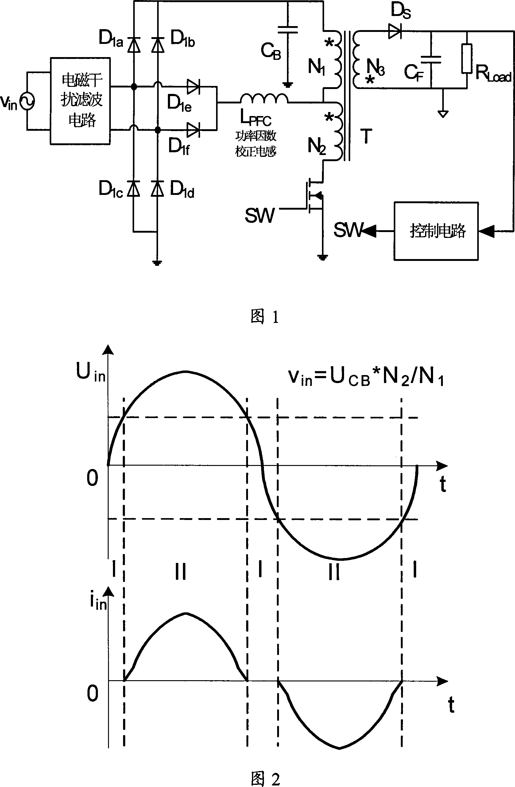
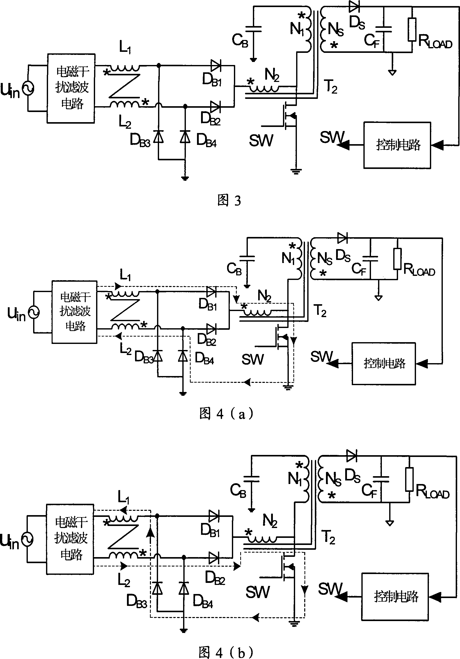
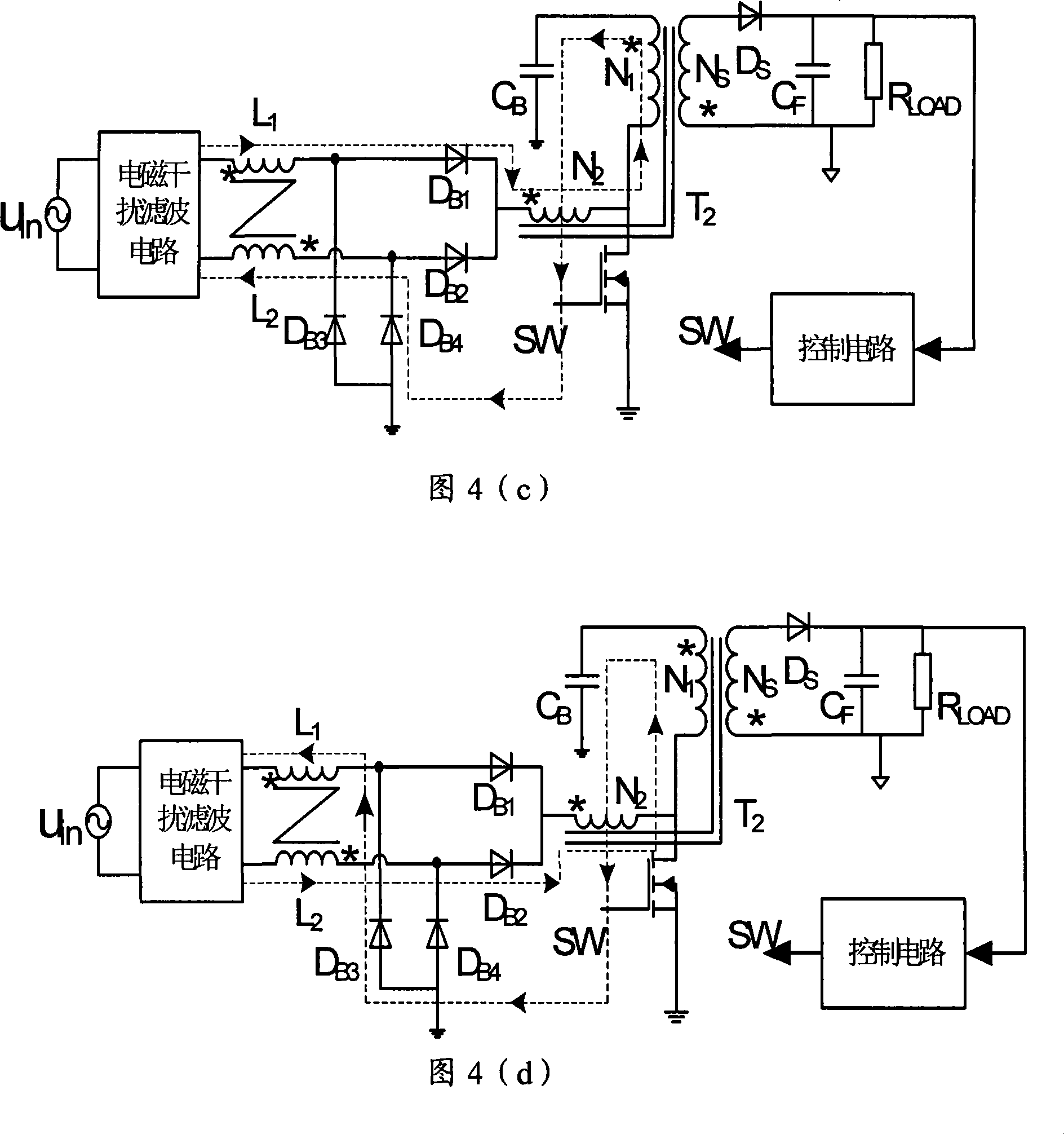
[0034] Based on the circuit shown in Figure 1, a PFC inductor L coupled with two windings is used 1 , L 2 , place it before the rectifier bridge, and at the same time, use the same transformer primary winding N 1 Mutually coupled second winding N 2 Feedback the voltage of the energy storage capacitor to suppress its voltage and make it lower than 400V; when the switch tube SW is turned on or off, in the power loop formed, there are only two diode voltage drops, and the conduction loss is low; the switch tube SW When disconnected, the PFC inductor L 1 , L 2 Part of the stored energy is charged to the energy storage capacitor, and the other part is directly transmitted to the secondary side through the transformer to improve the overall efficiency. The control circuit controls the turn-on and turn-off of the switch tube SW by detecting the output voltage, and can adopt constant frequency, flyback transformer T 1 Work in CCM or DCM mode; can also adopt frequency conversion c...


PUM


Abstract

This invention discloses a single-step power factor correction circuit for reducing switch loss, in which, a HF transformer includes two primary windings, and a pair of same-name ends are connected with the leakage of a switch tube, a mode of mutual couple of two windings is applied to put an inductance device for correcting input current waves in front of a rectifying bridge to improve the magnetic interference of the single-step PFC circuit at the same time when correcting power factors, when a switch tube is off, part of energy stored in the primary PFC inductor and the leakage inductor of the feedback winding is provided to the capacitor for charging and the other part is transmitted to secondary capacitor by the transformer directly so as to reduce loss brought with leakage inductance of the feedback winding and the switch loss and increases the efficiency.

Description

technical field [0001] The invention relates to a power factor correction circuit, in particular to a single-stage power factor correction circuit for reducing switch loss. Background technique [0002] The power factor correction circuit widely used at present is often the traditional two-stage power factor correction technology, but its circuit components are many, the cost is high, and the circuit is complicated, so it is not suitable for small and medium power applications. In order to reduce the cost of the two-stage power factor correction circuit, various single-stage power factor correction techniques have been proposed in recent years. A general single-stage power factor correction circuit automatically realizes the power factor correction function by controlling the inductor current to work in a discontinuous conduction mode. In order to achieve the balance of input and output power while ensuring the hold-up time of the power supply, a low-frequency capacitor is ...

Claims


Application Information

Patent Timeline
IPC IPC(8): H02M1/42H02M3/335
CPCY02B70/126Y02B70/10Y02P80/10
Inventor 马皓徐晔
Owner ZHEJIANG UNIV
Why Eureka
Try Eureka