
Plasma display panel and method for manufacturing same

A display panel and plasma technology, which is applied in the direction of AC plasma display panel, cold cathode manufacturing, electrode system manufacturing, etc., can solve difficult problems such as performance and characteristics, and achieve improved sputtering resistance, high-definition image quality, and reduced discharge The effect of lag time

Inactive Publication Date: 2008-03-05
PANASONIC CORP
View PDF2 Cites 2 Cited by
  • Summary
  • Abstract
  • Description
  • Claims
  • Application Information

AI Technical Summary

Problems solved by technology

However, in order to realize the protective performance of protecting the dielectric layer 106 from the impact of ions generated by the gas discharge, and to reduce the discharge voltage so that the responsiveness of the discharge is fast, the crystallographic structure of the protective film 107 or various physical properties are proposed. In the scheme of improving the characteristics, it is still difficult to say that the satisfactory performance and characteristics have been obtained.

Method used


Image

  • Plasma display panel and method for manufacturing same
  • Plasma display panel and method for manufacturing same
  • Plasma display panel and method for manufacturing same

Examples


Embodiment approach

[0053] One embodiment of the present invention will be described with reference to FIGS. 1A to 8 .

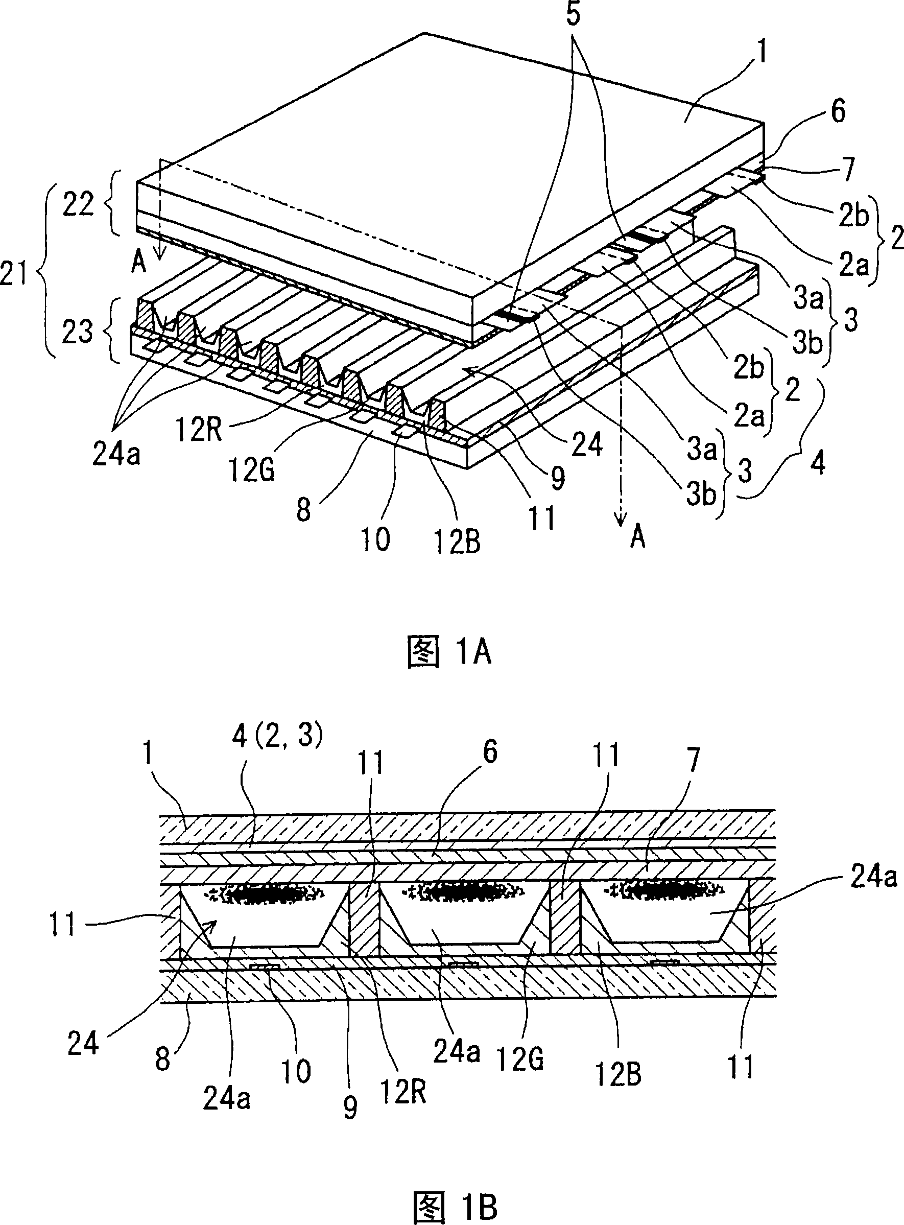
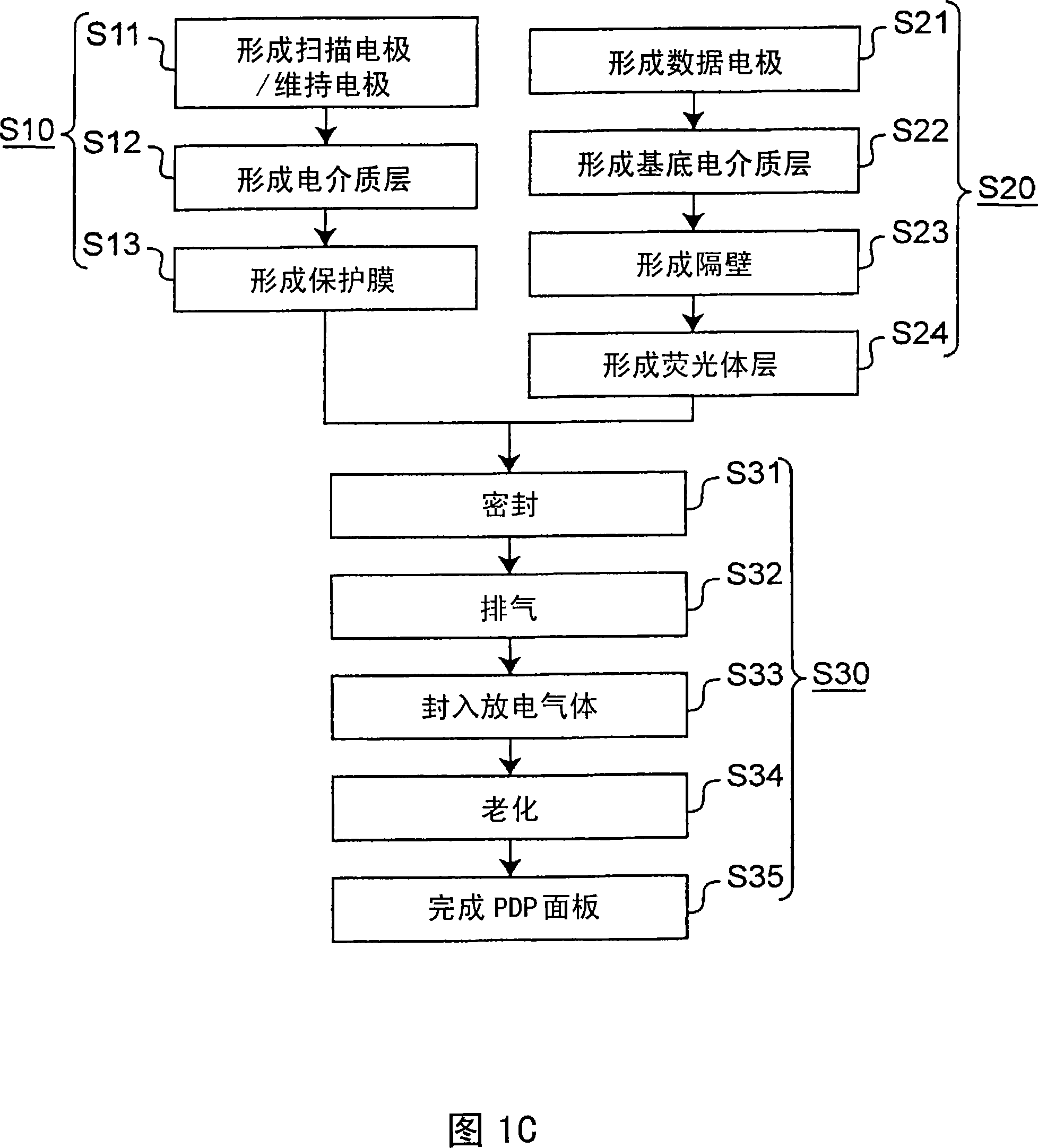
[0054] 1A is an exploded perspective view showing an enlarged part of the structure of an AC-type PDP in the embodiment of the present invention, FIG. 1B is an enlarged cross-sectional view showing the AA portion of FIG. 1A, and FIG. A flow chart of the manufacturing process is schematically described in the AC-type PDP manufacturing method. 9A and 9B as background technology, the structure of a general AC-type PDP has been described. 8, the row electrodes and column electrodes are arranged orthogonally, and the discharge space 24 is formed by the intersection of the two electrodes constituting the row and column of the pixel (pixel) and the partition wall 11 between the two substrates 1 and 8, but based on the structure of FIG. 1A and FIG. 1B will be described again.

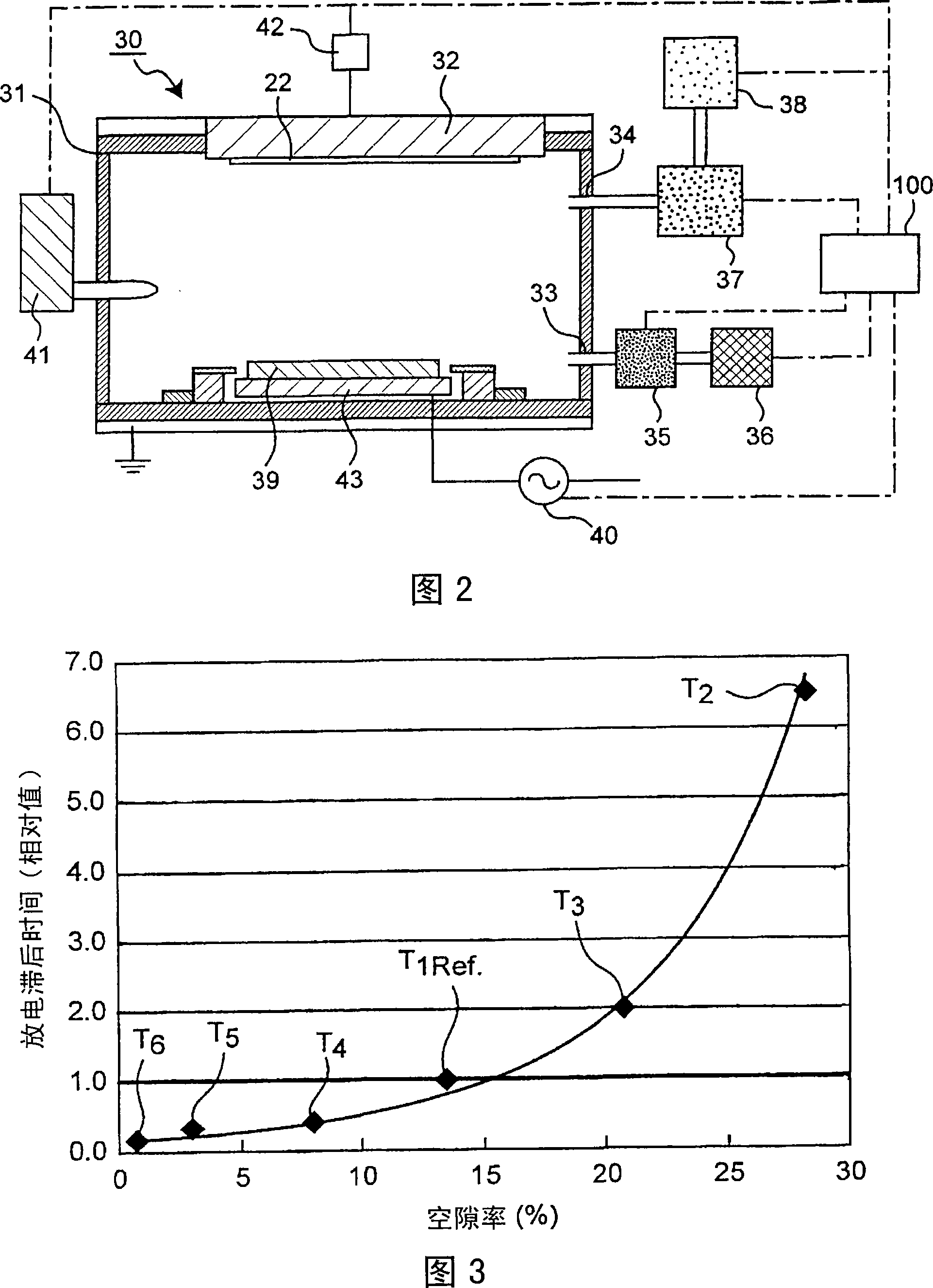
[0055] Next, FIG. 2 is a schematic configuration diagram of a film forming apparatus for forming the protec...


PUM


Abstract

Disclosed is a PDP (21) comprising a front plate (22) having a plurality of display electrodes (4) formed thereon and covered with a first dielectric layer (6) and a protective film (7), and a back plate (23) having a plurality of address electrodes (10) formed thereon so as to be perpendicular to the display electrodes (4) and covered with a second dielectric layer (a foundation dielectric layer (9)). In this PDP (21), the protective film (7) has a structure wherein granular crystals having large grain sizes gather together and the spaces between adjacent crystals are small.

Description

technical field [0001] The present invention relates to a plasma display panel (hereinafter referred to as a PDP) widely used as a flat panel display for displaying public information such as large televisions or advertisements and information, and a method for manufacturing the same. In particular, the present invention relates to a plasma display panel having a protective film capable of maintaining excellent display quality even with low output and long-time operation, and a method for manufacturing the same. Background technique [0002] In recent years, as a large flat-panel display device, a PDP that excites a phosphor to emit light by ultraviolet rays generated by a rare gas discharge and is used for image and video display has been developed targeting a large product with a diagonal of 1 m or more. The development of PDP is accelerated. As a display device for information processing represented by computers, or as a large-scale television receiver or a monitor for pu...

Claims


Application Information

Patent Timeline
Patent Type & Authority Applications(China)
IPC IPC(8): H01J11/02H01J9/02H01J17/04H01J17/49
CPCH01J9/02H01J11/40H01J11/12
Inventor 山下英毅大熊崇文早田博泷井谦昌中上裕一木村忠司寺内正治
Owner PANASONIC CORP
Learn More