Mask alignment making and aligning used for light scribing device

An alignment mark and mask alignment technology, which is applied in photoplate-making process exposure devices, microlithography exposure equipment, optics, etc. The effect of improved capture capability, high capture probability, and high repeatability

Active Publication Date: 2008-03-12
SHANGHAI MICRO ELECTRONICS EQUIP (GRP) CO LTD
View PDF0 Cites 25 Cited by
  • Summary
  • Abstract
  • Description
  • Claims
  • Application Information

AI Technical Summary

Problems solved by technology

[0004] The existing alignment marks, either have poor capture ability, need to add auxiliary mask alignment marks on the mask, and add more alignment scanning methods to perform step-by-step capture, thereby reducing the alignment efficiency; or The signal contrast of a ...

Method used


Image

  • Mask alignment making and aligning used for light scribing device
  • Mask alignment making and aligning used for light scribing device
  • Mask alignment making and aligning used for light scribing device

Examples


Embodiment 1

[0021] A mask alignment mark placed on the mask of the mask table and the reference plate of the workpiece table is a transmission alignment mark combination composed of a plurality of alignment mark branches, and the mark combination is used to provide The mask is optically aligned.

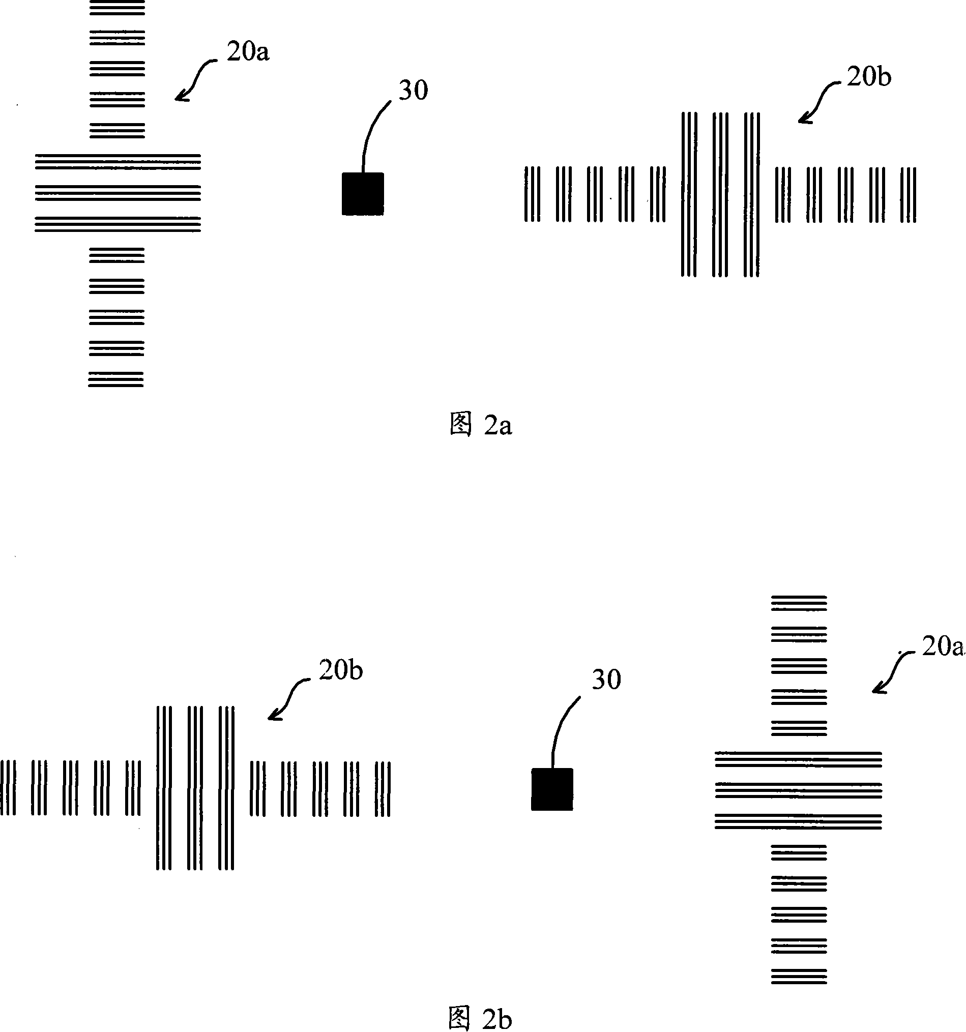
[0022] As shown in FIG. 2a and FIG. 2b, the mask alignment mark includes a first alignment mark branch 20a, a second alignment mark branch 30 and a third mark branch 20b, the first and third alignment mark branches 20a, 20b are mutually rotated by 90°; the graphics of the second alignment mark branch 30 in the transmission alignment mark on the workpiece table reference plate are distributed in the shape of square transmission holes, and the other two alignment mark branches 20a and 20b are used for alignment scanning Before, the aerial image corresponding to the second alignment mark branch 30 in the transmission alignment mark on the mask is scanned by scanning the aerial image corresponding t...

Embodiment 2

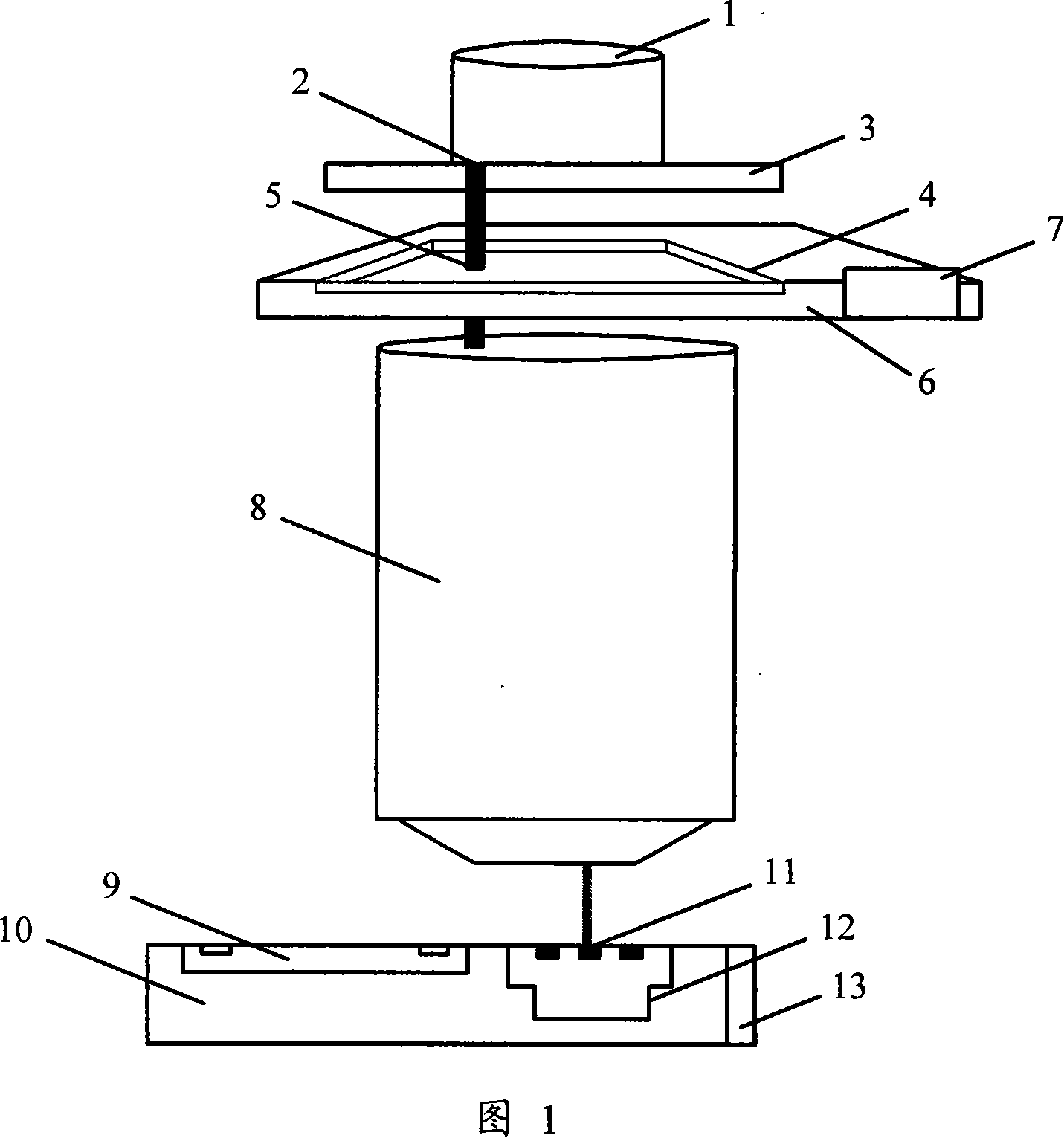
[0027] A method for aligning a photolithographic device. In the alignment system of the lithography apparatus shown in FIG. 1 , the alignment position is obtained from the model by calculating the parameters of the relationship model between the radiation and the relative position between the mask and the workpiece table.

[0028] The flow of the mask alignment method using the above-mentioned mask alignment marks will be described in detail below with reference to FIG. 1 to FIG. 4 . Point O in Figure 3 is the geometric center of the workpiece table, and the specific steps are as follows:

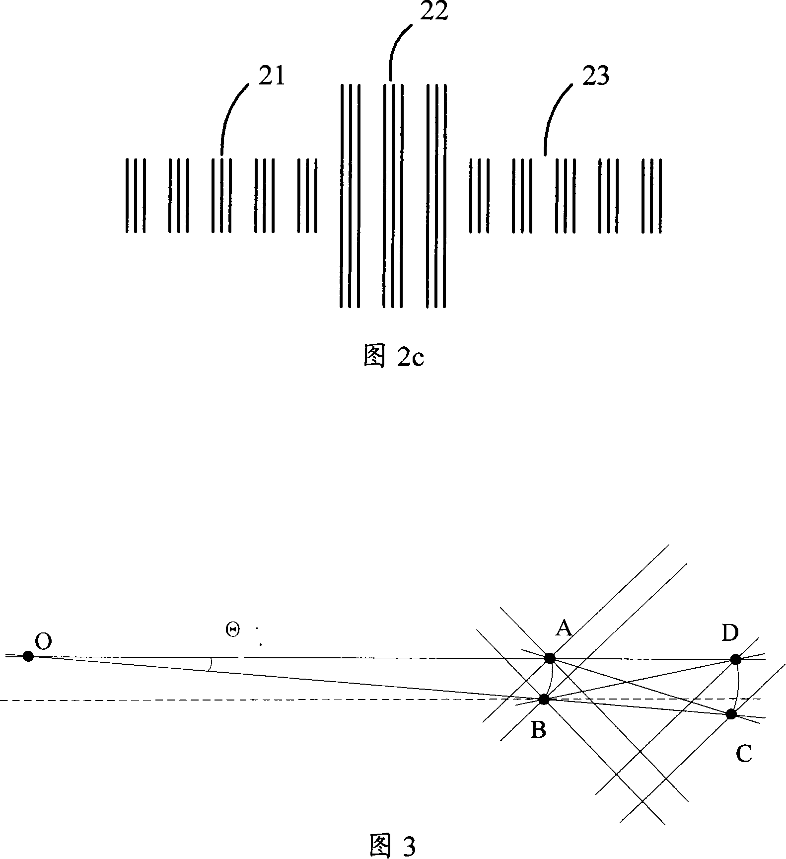
[0029] 1. Use the second alignment mark branch 30 in the transmission alignment mark 12 on the workpiece table reference plate to perform a rough scan on the second alignment mark branch 30 in the transmission alignment mark 5 on the mask to capture the entire transmission alignment mark, The approximate position of the transmission alignment mark is obtained, wherein the three alignment m...

Embodiment 3

[0037] Referring to Fig. 1 to Fig. 4, another method for aligning a lithographic apparatus of the present invention includes the following steps:

[0038] (a) Use the second alignment mark branch in the mask alignment mark on the workpiece table reference plate to perform rough capture scanning on the aerial image of the second alignment mark branch in the alignment mark on the mask, and use the detected calculating the radiation information, the position information of the mask and the position information of the workpiece table to obtain the coarse center position of the combination of transmission alignment marks;

[0039] (b) Use the first alignment mark branch on the workpiece table reference plate to perform single-layer or multi-layer rough scanning of the aerial image of the corresponding alignment mark branch on the mask in a direction perpendicular to it, and use the detected Calculating the radiation information, mask position information, and workpiece table positi...


PUM


Abstract

The present invention discloses a mask alignment mark and an alignment method. Partial structure of the mask alignment mark is different from the left part and longer as usual to enhance capacity of mark branches to capture mark scanning, increase success rate of coarse scanning, improve contrast of alignment information generated by the alignment scanning, elevate signal-to-noise ratio of information during alignment processing and heighten precision of mask alignment. The method of generating Moire fringe information by combining radial coarse scanning with tangential rotating coarse and fine scanning improves alignment scanning efficiency. A method of generating Moire fringe information by combining coarse and fine scanning along a raster direction in an alignment mark branch approximately vertical with two vertical directions improves alignment scanning efficiency.

Description

technical field [0001] The invention relates to an alignment technology of a lithography device, in particular to a mask alignment mark used for a lithography device and an alignment method using the alignment mark. Background technique [0002] In industrial devices, due to the need for high precision and high productivity, a large number of high-speed real-time signal sampling, data acquisition, and real-time signal processing systems are distributed. Among them, the real-time signal processing system needs to adopt effective information processing models and methods to meet the requirements of high precision and high efficiency. Devices with this requirement include: integrated circuit manufacturing lithography device, liquid crystal panel lithography device, photomask marking device, MEMS / MOEMS lithography device, advanced packaging lithography device, printed circuit board lithography device, printed circuit board processing device etc. [0003] In the previous above-...

Claims


Application Information

Patent Timeline
IPC IPC(8): G03F7/20G03F9/00
Inventor 李焕炀陈勇辉宋海军
Owner SHANGHAI MICRO ELECTRONICS EQUIP (GRP) CO LTD
Why Eureka
Try Eureka