Automatic clamp-on ultrasonic therapeutic device

An ultrasonic therapy and clip-on technology, applied in the field of medical devices, can solve the problems of inability to effectively control the target tissue, complicated operation process, increase the treatment cost, etc., and achieve the effect of reducing the possibility of blood transfusion, lowering the treatment cost, and saving the treatment cost.

Inactive Publication Date: 2008-03-19
RONGHAI SUPERSONIC MEDICINE EN
View PDF5 Cites 10 Cited by
  • Summary
  • Abstract
  • Description
  • Claims
  • Application Information

AI Technical Summary

Problems solved by technology

[0004] Although the ultrasonic devices disclosed in the above-mentioned U.S. patents have played a hemostasis role in the removal of vascular-rich tissues in surgical operations to a certain extent, there are certain limitations in the use of these devices: first, the operator needs to use the surgical incision It is different from continuously moving the large ultrasonic transducer by hand at the same angle, the operation process is very complicated, and it is easy to cause misoperation; second, when the tissue to be treated is relatively soft and loose, the pressure generated by the above-mentioned device on the target tissue It will not be enough, so the target tissue cannot be effectively controlled. If the target tissue cannot be controlled, the ultrasonic energy will not reach the target tissue, and the expected hemostatic effect will be invalidated; thirdly, because the above-mentioned device can only form a focal point in the lesion tissue, And usually the ultrasonic energy will also be attenuated on the acoustic channel, so during the treatment process, it takes a lot of time when coagulation necrosis occurs in thicker tissues (such as liver and spleen), which increases the treatment cost

Method used


Image

  • Automatic clamp-on ultrasonic therapeutic device
  • Automatic clamp-on ultrasonic therapeutic device
  • Automatic clamp-on ultrasonic therapeutic device

Examples


Embodiment 1

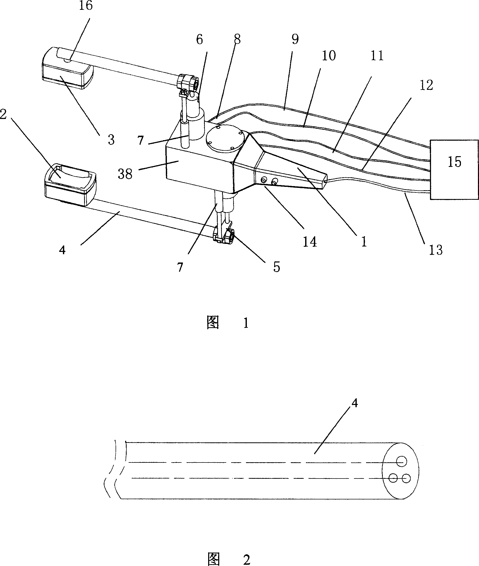
[0040] As shown in Fig. 1, the present invention includes a handle 1, an ultrasonic therapy head, a motion unit, and a support unit for the ultrasonic therapy head.

[0041] The movement unit adopts a hydraulically driven telescopic unit, and the telescopic unit is fixed on the handle 1, which includes a hydraulic cylinder 38, a multi-stage piston rod 6 that can be extended step by step on the hydraulic cylinder 38, a support rod 7, and a terminal for sealing liquid. Cover 8, hydraulic control system 15.

[0042] The hydraulic control system 15 communicates with the hydraulic cylinder 38 through the delivery pipes 9, 10, 11, 12, the delivery pipes 9, 11 deliver liquid to the upper and lower hydraulic cylinders, and the delivery pipes 10, 12 deliver the liquid in the hydraulic cylinder 38 under pressure As far as the hydraulic control system 15 is concerned, the telescopic direction of the piston rod is parallel to the central axis of the ultrasonic treatment head, and the pist...

Embodiment 2

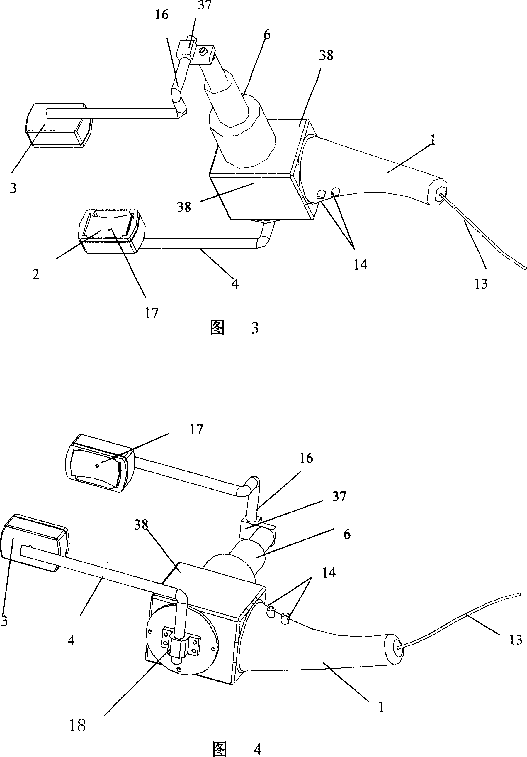
[0051] As shown in Figures 3 and 4, the difference between this embodiment and Embodiment 1 is that only one ultrasonic treatment head is connected to the piston rod 6 among the two ultrasonic treatment heads arranged oppositely, and the other is fixed by the connecting pipe 4. A member 18 is secured to the underside of the end cover 8 of the hydraulic cylinder.

[0052] The ultrasonic treatment head that links to each other with piston rod 6 is connected by connecting pipe 4 through adapter sleeve 37, and adapter sleeve 37 is made to be parallel with the ultrasonic treatment head central axis and extends a certain distance to the direction that two treatment heads approach, so just can Reduce the distance between the two ultrasonic treatment heads, and keep the two ultrasonic treatment heads parallel. At the same time, because the adapter 16 can rotate freely, the two ultrasonic therapy heads can be connected to the connecting pipe 4 through the adapter 16 .

[0053] Simulta...

Embodiment 3

[0058] In this embodiment, except for the motion unit, other structures are the same as those in Embodiment 2.

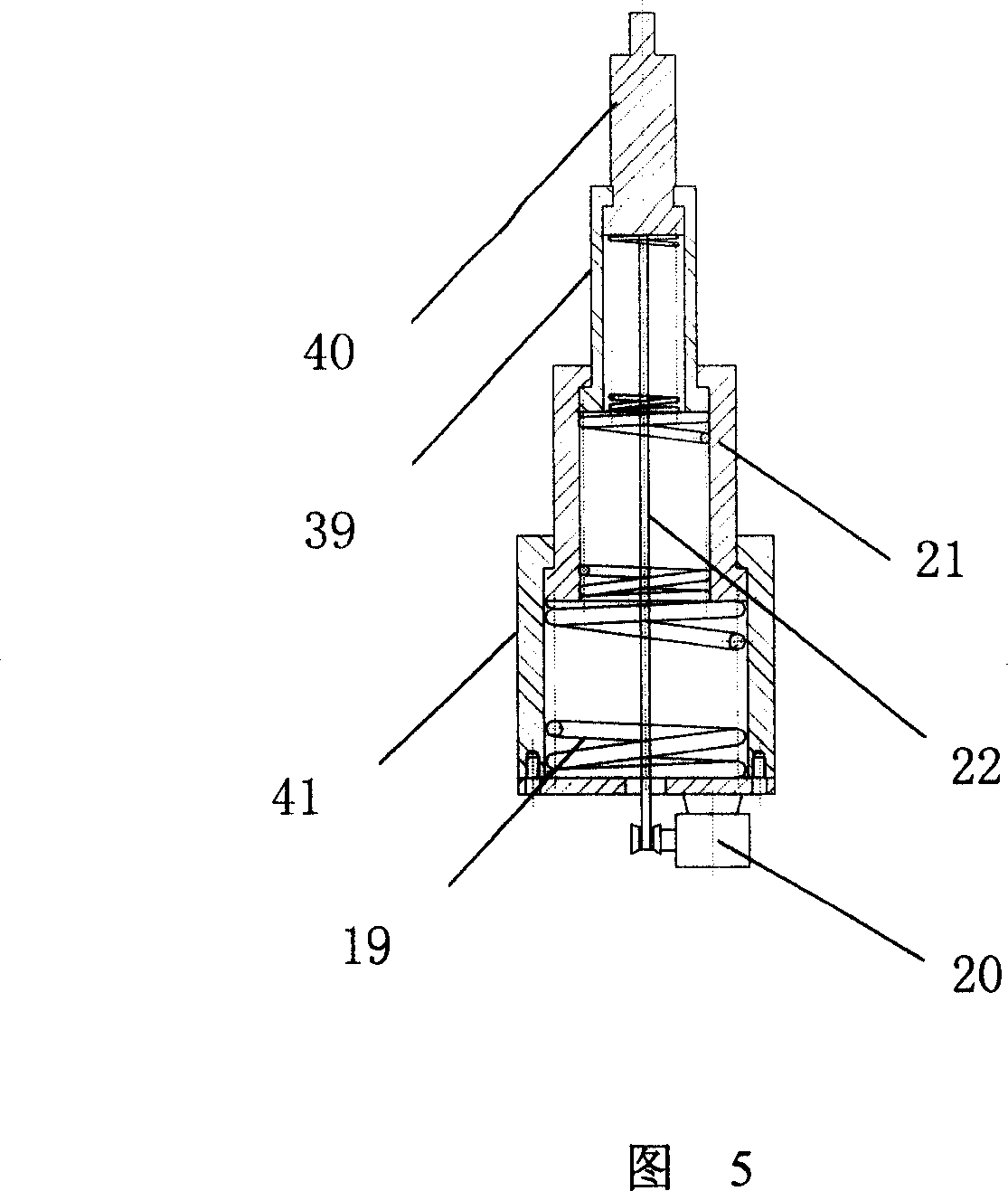
[0059] The motion unit in this embodiment adopts a motor-driven multi-stage spring structure.

[0060] As shown in FIG. 5 , the movement unit includes multi-stage telescopic rods that can be extended step by step, springs 19 placed in the telescopic rods of each stage, a motor 20 , and a soft rope 22 . In this embodiment, the multi-stage telescopic rod adopts three stages, that is, the first-stage telescopic rod 21 , the second-stage telescopic rod 39 , and the last-stage telescopic rod 40 . Every level telescopic link is placed on the spring 19 in the upper stage telescopic link respectively. Wherein, the primary telescopic rod 21 is placed on the spring 19 in the support sleeve 41, the secondary telescopic rod 39 is placed on the spring in the primary telescopic rod 21, and the final telescopic rod 40 is placed on the spring in the secondary telescopic rod 39. s...


PUM


Abstract

The present invention relates to an automatic clamp suture ultrasound treatment equipment, comprising a ultrasound treatment head. Wherein, two ultrasound treatment heads are arranged at opposite positions. The central axes of the two ultrasound treatment heads are superposable. Anyone of the two ultrasound treatment heads or both of the two ultrasound treatment heads are connected with the moving unit which is relatively quiescent all the time with the two ultrasound treatment heads in the moving process. The moving unit can adopt the shrinking unit which is driven by fluidic pressure or motor, or adopt mechanical open-close unit etc. The present invention has a simple structure and low treatment cost, is convenient to operate, and can make focus organization rapidly happen coagulation necrosis in the treatment process. Besides, the present invention can be widely used to cure all kinds of illnesses.

Description

technical field [0001] The invention belongs to the technical field of medical devices, and relates to an ultrasonic treatment device, in particular to an automatic clamping type ultrasonic treatment device. Background technique [0002] Ultrasound, especially high-intensity focused ultrasound, has been widely used in the medical industry to diagnose and treat patients. High-intensity focused ultrasound therapy technology can form high-intensity and continuous ultrasonic energy on the lesion by focusing the ultrasound, thereby producing transient high-temperature effects (60°C-100°C), cavitation effects, mechanical effects, and sonochemical effects. Cell membrane, nuclear membrane rupture, protein coagulation, selective coagulation necrosis of lesion tissue, and loss of ability to proliferate, infiltrate and metastasize the lesion. In addition, high-intensity focused ultrasound treatment technology can be used for tumor resection, and can also effectively treat other disease...

Claims


Application Information

Patent Timeline
Patent Type & Authority Applications(China)
IPC IPC(8): A61N7/02A61N7/00A61B17/12A61B17/32A61B18/00
CPCA61B2017/2808A61B17/320092A61N2007/0078A61B2017/00513A61N7/00A61B2017/320095A61B2017/320094
Inventor 黄小林毛爱华燕思源汪海
Owner RONGHAI SUPERSONIC MEDICINE EN
Why Eureka
Try Eureka